


Commonly used driving motor types and principles
Based on the basic performance requirements of new energy vehicle drive motors, the current commonly used drive motor types mainly include three categories, namely AC asynchronous motors, permanent magnet synchronous motors and switched reluctance motors. At present, in the statistics of supporting models of various car companies, the types of drive motors selected by each model are also different.
Therefore, it is very important to understand the structure, working principle, and performance advantages and disadvantages of the drive motor in order to select the type of motor equipped with a new energy vehicle.
AC asynchronous motor
1. AC asynchronous motor structure
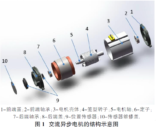
AC asynchronous motors, also known as induction motors, mainly include stators, rotors, motor shafts, front and rear bearings, end covers, position sensors, temperature sensors, low-voltage wiring harnesses and high-voltage power wiring harnesses. The stator is composed of a stator core and a three-phase winding; the rotor is usually a cage rotor, including a rotor core and a cage winding. Depending on the power of the motor, water cooling or air cooling will be selected. (figure 1)
2. Working principle of AC asynchronous motor
(1) Driving principle of AC asynchronous motor
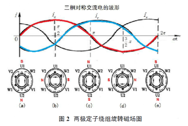
1) The stator provides a rotating magnetic field. To drive and provide torque for an AC asynchronous motor, three-phase AC power needs to be passed through the stator coil to generate a continuously rotating magnetic field (the magnetic field speed is ns). AC asynchronous motors require that the three-phase windings of the stator must be symmetrical, and the stator cores must have a 120-degree electrical angle difference in space; the current flowing into the three-phase symmetrical windings must also be symmetrical, with the same size and frequency, and a phase difference of 120 degrees. The rotational speed of the rotating magnetic field is shown in formula (1).
ns=60f/p(1)
In the formula, ns is the speed of the rotating magnetic field (also known as synchronous speed), r/min; f is the frequency of the three-phase alternating current, Hz; p is the number of magnetic pole pairs. For the drive motor that has been designed and finalized, the logarithm of the magnetic level has been determined, so the factor that determines the rotation speed of the magnetic field is the frequency of the three-phase alternating current. Since the power grid frequency in my country is f=50Hz, there is a linear relationship between the motor speed and the number of magnetic pole pairs. (figure 2)
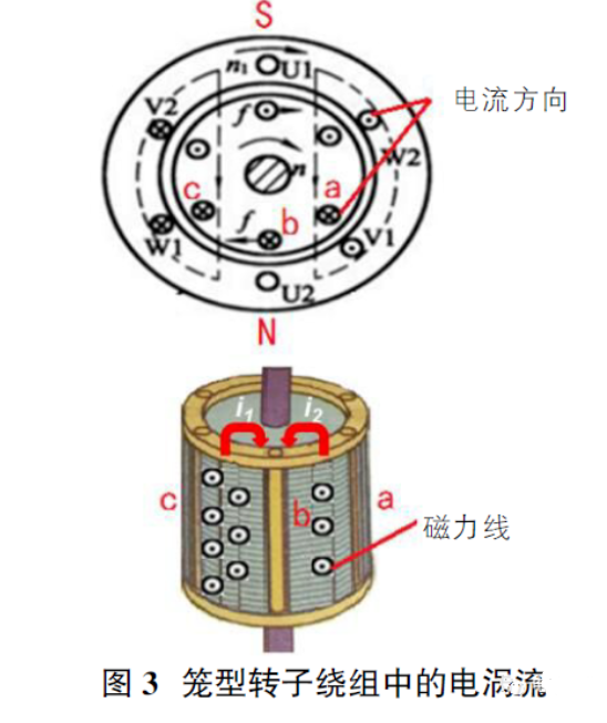
2) Cage rotors provide induced eddy currents. Since the stator provides a rotating magnetic field, eddy currents are induced on the cage rotor conductors, as shown in Figure 3. In the magnetic conduction area between the cage-shaped winding conductors c and b, there are outward magnetic force lines, and the magnetic force lines are strengthened under the action of the rotating magnetic field, so the i1 eddy current will be induced on the conductors c and b; similarly , The weakened magnetic field lines in the area of conductor a and conductor b will induce i2 eddy current on the conductor. Under the action of the rotating magnetic field of the stator, the current on the conductor b will cause the conductor of the cage winding b to be subjected to electromagnetic force, so that the rotor will generate electromagnetic torque and rotate. The rotating rotor gradually catches up with the rotating magnetic field, spinning at a speed n slightly slower than the "synchronous speed ns" of the magnetic field. The phenomenon that the rotation speed n of the rotor is slightly slower than the speed ns of the stator magnetic field is called the slip of the rotor. This asynchronous slip causes the cage-shaped rotor conductor to continuously cut the magnetic field lines to generate induced eddy currents. Therefore, on the rotor , Electric energy is converted into mechanical energy to ensure continuous external output.
(2) Working principle of power generation of AC asynchronous motor
According to Faraday's law of electromagnetic induction, when a part of the conductor of a closed circuit cuts the movement of the magnetic field line in the magnetic field, an induced current will be generated in the conductor, and the generated electromotive force becomes the induced electromotive force. In an AC asynchronous motor, when the motor is used as a generator, the three-phase current in the stator is the excitation current, which provides a magnetic field, and the winding on the rotor provides a conductor. When the external mechanical force, such as the drive shaft of a car, drives the rotor shaft, the rotor is driven During motion, if the rotational speed on the rotor is higher than the synchronous rotational speed of the stator's rotating magnetic field, the AC asynchronous motor is a generator at this time, and the direction of the rotor cutting the rotating magnetic field at this time is opposite to that of the rotor working as a driving motor, so the direction of the electromotive force induced by the rotor Also the opposite. During the power generation process, the rotor of the motor is subjected to an electromagnetic resistance torque opposite to that of the external force, which makes the rotor speed drop.
3. Advantages, disadvantages and application range of AC asynchronous motor
The advantage of the AC asynchronous motor is that the output torque can be adjusted in a wide range, and the output torque can be forced to increase in a short time when accelerating or climbing a slope. The electric drive vehicle of the permanent magnet synchronous motor usually increases the torque by adding a gearbox mechanism to increase the speed. . However, the disadvantage of AC asynchronous motor is that due to the unilateral excitation of the motor, the starting current is large, and the current required to generate unit torque is relatively large, and there is reactive excitation current in the stator, so the energy consumption is larger than that of the permanent magnet synchronous motor, and the power factor lags behind. ; Overload phenomenon often occurs in heavy-duty driving; the structure is relatively complex, its control technology requires high requirements, and the manufacturing cost is high; the power density is relatively low. At present, most electric drive vehicles developed in the United States use AC asynchronous motors as drive motors.
Permanent Magnet Synchronous Motor
1. The structure of permanent magnet synchronous motor
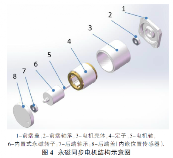
The structure of permanent magnet synchronous motor includes stator, rotor, motor shaft, front and rear bearings, end cover, cooling water channel, position sensor, temperature sensor, low-voltage wiring harness and power wiring harness. The stator is composed of stator core and three-phase winding; the rotor is composed of permanent magnet poles and iron core, and the iron core is made of silicon steel sheets. According to the arrangement of permanent magnets in the rotor, it mainly includes surface-protruding permanent magnet rotors, surface-embedded permanent magnet rotors and built-in permanent magnet rotors. At present, new energy motors commonly use built-in permanent magnet rotors. (Figure 4)
2. Working principle of permanent magnet synchronous motor
(1) The driving principle of permanent magnet synchronous motor
The rotating magnetic field is provided by the stator, and the method and speed of the magnetic field are the same as those of the AC asynchronous motor. The poles are provided by the permanent magnets of the rotor. In this way, the rotating magnetic field generated by the stator forms a loop with the poles of the permanent magnet of the rotor and the iron core of the rotor. According to the principle of minimum reluctance, that is, the magnetic flux always closes along the path of minimum reluctance, and the electromagnetic force of the rotating magnetic field is used to pull the rotor to rotate, so the permanent magnet rotor will rotate synchronously with the rotating magnetic field generated by the stator, thereby driving the motor shaft to rotate.
(2) Power generation principle of permanent magnet synchronous motor
According to Faraday's law of electromagnetic induction, part of the conductor of the closed circuit is provided by the three-phase stator winding, and the magnetic field is provided by the permanent magnet on the rotor. When the external torque drives the rotor to rotate, a rotating magnetic field is generated, which cuts part of the conductor in the three-phase stator winding. Inductive three-phase symmetrical current is generated, at this time the kinetic energy of the rotor is converted into electrical energy, and the permanent magnet synchronous motor works as a generator.
3. Advantages, disadvantages and application range of permanent magnet synchronous motor
The advantages of permanent magnet synchronous motors are small size, light weight, high power density, low energy consumption, low temperature rise, and high efficiency compared with asynchronous motors. According to the requirements, it can be designed as a structural motor with high starting torque and high overload capacity. The permanent magnet synchronous motor is strictly synchronized and has good dynamic response performance. It is suitable for frequency conversion control. Adjusting the current and frequency can adjust the torque and speed of the motor in a large range. However, the permanent magnet material in the permanent magnet synchronous motor is usually made of NdFeB strong magnetic material, which is relatively brittle and hard, and may be broken when subjected to strong vibration; A magnetic recession occurs, causing a drop in power. At present, permanent magnet synchronous motors are widely used in new energy vehicle motors. The Asian and European new energy markets mainly use permanent magnet synchronous motors as new energy motors.
Switched Reluctance Motor
1. Structure of switched reluctance motor
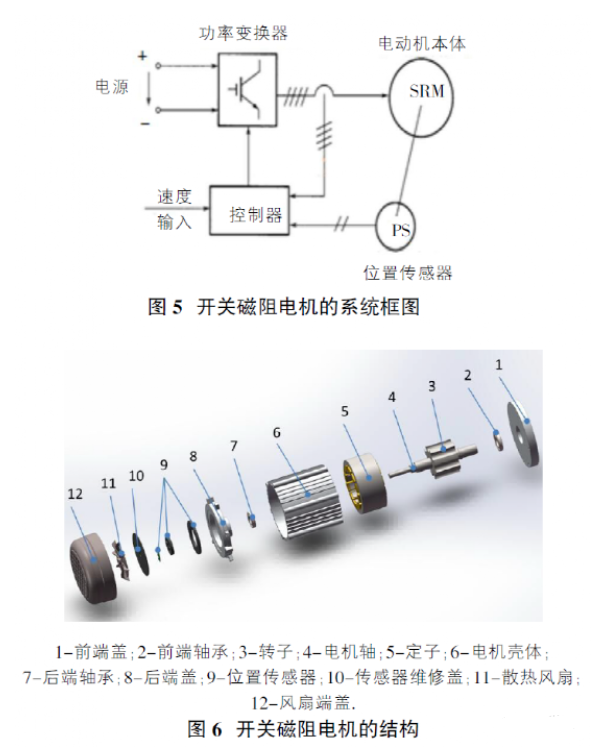
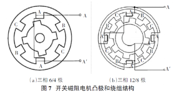
Switched reluctance motor is a typical mechatronic motor, also known as "switched reluctance motor drive system", this motor mainly includes four parts: switched reluctance motor body, power converter, rotor position sensor and controller, such as Figure 5 shows. The main structure of the switched reluctance motor body includes a stator, a rotor, a position sensor, front and rear bearings, front and rear end covers, and a motor housing, as shown in Figure 6. Wherein, the stator includes a stator core and a winding. Both the stator core and the rotor adopt a salient pole structure. The stator salient pole core and the rotor are both made of silicon steel sheets. The windings are arranged on the stator salient poles, and the rotor has no windings and permanent magnets.
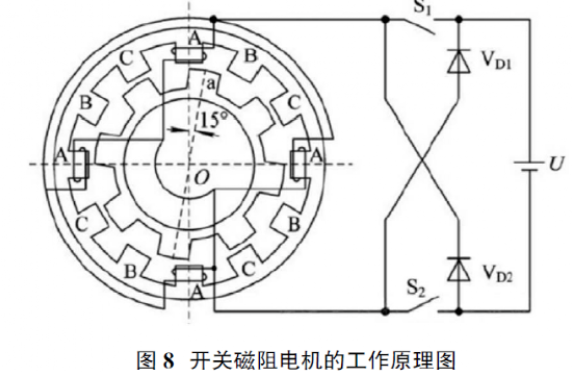
The three-phase 6/4 pole structure shows that the motor stator has 6 salient poles, and the rotor has a salient pole, in which the concentrated windings on the two symmetrical salient poles of the stator are connected in series to form a phase, and the number of phases is the number of stator salient poles /2, as shown in Figure 7(a). The three-phase 12/8 pole structure shows that the stator of the motor has 12 salient poles, and the rotor has 8 salient poles. Among them, the windings on the four symmetrical salient poles of the stator are connected in series to form a phase, and the number of phases is the salient pole of the stator. number/4, as shown in Figure 7(b).
The more phases of the switched reluctance motor, the smaller the step angle, the more stable the operation, the more conducive to reducing torque fluctuations, but the more complicated the control, resulting in more main switching devices and higher costs.
Calculation of step angle, see formula (2):
α=360°×(number of stator poles-number of rotor poles)/(number of stator poles) (2) such as a three-phase 6/4 pole motor, its step angle a=360°×2(/6×4)=30 °.
2. Working principle of switched reluctance motor
(1) The driving principle of switched reluctance motor
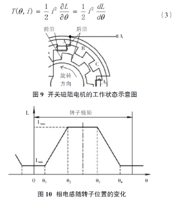
From the working principle diagram of the three-phase 12/8-pole switched reluctance motor in Figure 8, it can be known that when the main switches S1 and S2 of the winding current control of the A phase are closed, the A phase is energized and excited, and the magnetic field force generated in the motor takes OA as the axis The radial magnetic field of the magnetic field is curved at the air gap passing through the salient poles of the stator and the salient poles of the rotor. The salient poles are affected by the pulling force of the magnetic field, so that the rotor pole axis Oa coincides with the stator pole axis OA, thereby generating an electromagnetic torque of reluctance nature, which makes the rotor rotate counterclockwise. Turn off the A-phase power supply and set up the B-phase power supply. At this time, the magnetic field inside the motor rotates 30 degrees, and the rotor continuously rotates 15 degrees counterclockwise under the action of the electromagnetic pull at this time. If the ABCA phase windings are energized in sequence, the rotor will continue to rotate in the counterclockwise direction; when the stator windings in each phase are energized once, the stator magnetic field turns 3×30 degrees, and the rotor turns a rotor pole pitch 3×15 degrees (that is, 360 degrees/number of rotor salient poles). If the ACBA phase windings are energized sequentially, the rotor will turn in a clockwise direction. Switched reluctance motors are independent of the direction of the current and depend on the order in which the stator phase windings are energized. In the actual operation of multi-phase motors, it is often the case that two-phase or more than two-phase windings are turned on at the same time.
(2) Working principle of power generation of switched reluctance motor
The phase inductance of the switched reluctance generator has three states in the working state, the excitation state, the freewheeling state and the power generation state. The L waveform of the phase inductance is shown in Figure 10.
In Fig. 9, the angle θ is defined as the angle between the axis of the tooth pole of the rotor and the axis of the slot of the stator. When the rotor tooth pole axis coincides with the corresponding stator tooth slot axis, the phase inductance is the smallest (defined as θ=0°); until the leading edge of the rotor salient pole meets the trailing edge of the stator salient pole (θ=θ1), the winding phase The inductance always keeps Lmin constant; when the rotor continues to rotate, the salient poles of the rotor begin to coincide with the salient poles of the stator until the trailing edge of the salient pole of the rotor coincides with the trailing edge of the salient pole of the stator (at this time θ=θ2), the phase inductance of the winding is here The range rises linearly until the maximum value Lmax; when the rotor continues to rotate until the leading edge of the salient pole of the rotor coincides with the leading edge of the salient pole of the stator, θ=θ4 at this time, and the inductance of this phase continues to Lmax.
According to the basic theory of electromagnetic field, with the existence of the magnetic field, the electromagnetic torque of the motor rotor exists simultaneously, which can be expressed as formula (3).
If the windings of the switched reluctance motor are switched on and off between θ3 and θ4, the motor operates as a generator. At this time, a current is formed in the inductance drop area, then dL/dθ<0, at this time, the phase winding has current passing through, and a braking torque (T(θ,i)<0) is generated. If the external mechanical force maintains the motor rotation, Then the motor absorbs mechanical energy and converts it into electric energy output, and at this time the switched reluctance motor is in the generator working mode.
3. Advantages, disadvantages and application range of switched reluctance motor
The advantages of switched reluctance motors are simple and reliable structure, good starting performance, high efficiency, low cost, speed regulation by changing the turn-on and turn-off angles and voltage, and has a wide speed regulation range and capability. The disadvantages of switched reluctance motors are large torque ripple and high noise. Currently used in some small electric drive vehicles, such as electric drive four-wheel scooter, patrol car and so on.
epilogue
According to the performance requirements of the new energy vehicle drive motor itself, the drive motors selected by the models on the market are also different. This paper describes the structure and working principle of AC asynchronous motor, permanent magnet synchronous motor and switched reluctance motor, which are commonly used in new energy drive motors, and will help to better understand drive motors.
Moreover, due to the different structures and principles of each type of motor, the scope of application is also very different. According to the national industrial strategic plan, the research on the electric drive system of environmentally friendly new energy vehicles will become more and more extensive, and the types and technical levels of motors will also continue to improve.
 XINDA
XINDA