AC asynchronous motor basics
1. Motor model:
1. The model of small and medium-sized motors generally consists of 6 parts:
|
1 |
2 |
3 |
4 |
5 |
6 |
A. The series code of the motor 1. The series code of the motor
1) Y means ordinary single-speed motor
2) For other series of motors, add 1-3 letters after Y to indicate its characteristics, such as ordinary multi-speed
The motor uses "YD", "YH" to indicate high slip rate, etc.
B. Serial number of the design plan
1) The Arabic numerals immediately following the letter are the design serial number of the motor, such as "2" in Y2 is the design serial number. No need to write 1, write more than 2.
2. Seat number:
Directly write the center height of the motor in the new standard, and the unit is mm.
1) For example, in the motor model Y2-160M2-2WF, "160" means that the center height of the motor is 160mm.
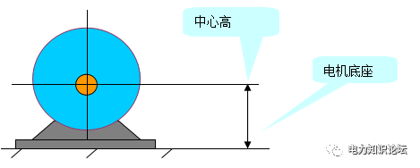
center height diagram
2) Classify motors by center height:

The base length is generally divided into 3 grades. Long, medium and short are represented by L, M and S respectively. 3. Base length code
For a base with only one length, for example: a motor with a center height of 80, there is no such item, which is recorded as
Y801-4.

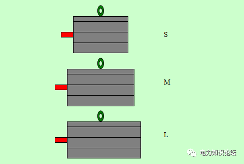
Schematic diagram of three different length bases with the same center height ( S, M, L)
4. Core length code:
The codes of the same type of frame and different iron core lengths are represented by numbers 1, 2, 3, ..., and the larger the number, the longer the iron core and the greater the power. Imported or exported motors are no exception, indicated by A, B, C, .... When there is only one length, this part does not need to appear.
●Y series and its derivative products
A. There is a base length code, and the iron core length code appears as the foot mark of the base length code, for example: Y160M 2 -4

B. There is no base length code, and the iron core length code appears as the footmark of the center height (frame number), for example: Y80 2 -4

●Y2 series and its derivative products appear in normal character size, for example: Y2-180M 2 -6 or Y2-80- 2 -4, all fonts are the same size.

5. Number of poles:
Give the number of poles of the stator magnetic field of the motor in digital form (indicated by P), such as Y802-4, "4" means 4 poles.
Then the rotation speed of the stator magnetic field (synchronous speed, unit r/min) n s, ns=60f/p.
2-pole electric synchronous speed is 3000r/min, 4-pole electric synchronous speed is 1500r/min, 6-pole electric synchronous speed is 1000r/min....
If it is a multi-speed motor, use "/" to separate each speed, such as YD160-8/6/4.
6. Special environment code:
Use specific letters to indicate the special working environment that the motor is applicable to. Generally no.

7. Example of model interpretation:
Example 1: Y2-160M2-2WF
Interpretation: Y series basic three-phase AC asynchronous motor; the second design (or second generation); center height (frame size) is 160mm; medium length frame; No. 2 core length; 2 poles; available in It is used outdoors and in working environments with corrosive gases.
Example 2: YZR355L1-10TH
Interpretation: Y series three-phase asynchronous motor with wound rotor for metallurgical lifting; center height (frame size) is 355mm; long machine base; No. 1 iron core length; 10 poles; can be used in hot and humid environment.
2. Rated power P N:
The rated power of the motor PN refers to the three-phase symmetrical alternating current with rated voltage and frequency. Under the specified environmental conditions, the shaft power (mechanical power) that can be output normally for a long time is also called capacity. The unit is kilowatt (KW), and imported motors also have horsepower (HP).
1HP=0.75KW
1KW=1.35HP
3. Rated voltage U N , rated frequency f N , and wiring method:
1) Rated voltage, rated frequency and wiring mode are interrelated.
The rated voltage is the voltage to ensure the normal operation of the motor. It often refers to the line voltage, and the unit is V or KV. We commonly use 220V, 380V, 3KV, 6KV, and 10KV.
The actual power supply voltage used by the motor is generally between 95% and 105% of UN. When the motor uses two voltages, use "/" to separate them, such as: 220/380V.
2) Rated frequency
The rated frequency is the frequency that guarantees the specified speed of the motor output, which is 50HZ in my country.
3) Motor wiring
The motor wiring generally has a star (Y) and a delta (△), and most of the motor junction boxes have 6 taps, and the beginning and end of the same phase are represented by U1U2, V1V2, and W1W2 respectively.
According to the relevant standards of small motors (low voltage) in my country, the voltage connected to motors of 3KW and below is 220V
When it is connected to △ shape, when it is 380, it is connected to Y shape. In general, when the motor above 3KW is connected to the power supply as shown in the figure below, the rotation of the shaft should be clockwise when viewed from the extension end of the main shaft.
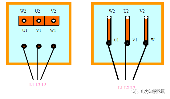
Ordinary sonic small low-voltage motor wiring
4. Rated current:
The rated current is the input line current of the stator when the motor is added with rated voltage and frequency to output rated power, and the unit is ampere (A). For small motors IN≈2PN, it is the most important parameter for selecting power distribution equipment and power supply equipment. The expression is In=Pn/Unηcos∮.
5. Rated speed:
The rated speed is the voltage of the motor plus the rated frequency, the rotor speed when the rated power is output, and the unit is r/min. Due to the principle of the motor, the rotor speed n is always smaller than the speed n1 of the magnetic field, which is also the reason why the motor is called an asynchronous motor. Usually, the slip S is used to indicate the difference between the motor speed n and the rotating magnetic field speed n1:
S=(n1-n)/n1
So: n=(1-S)n1
6. Insulation grade:
Insulation class includes heat resistance class. Indicates the level of voltage and temperature capability that the motor insulation material can withstand. As shown in the table below:
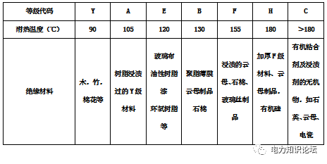
7. Shell protection level:
It refers to the ability of the motor casing and junction box to protect the motor circuit. Commonly used Ipxy is given, x and y are numbers, x ranges from 0-6, 7 levels, representing the ability to prevent solids, and the size of solids that cannot enter the motor (the last level is not available in our country); y ranges from 0-8, 9 grades, representing the ability to prevent liquids, the state that water cannot enter the inside of the motor. The higher the number, the greater the protection ability.
First Digit - Solids Resistance - Dimensions of solids that cannot enter
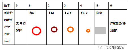
The second digit - water resistance - can not enter the state of water inside the machine

8. Working system:
Refers to the situation that the motor is under load during work, including the timing of walking, loading operation, braking, idling, and shutdown. Our country stipulates 10 kinds, represented by S1-S10 codes.
1) S1 long-term working system, the rated load of the motor works continuously.
2) S2 short-time work system, when this type of motor is cold, it will run with load for a specified time (there are 4 time limits of 10, 30, 60, and 90 minutes, and one of the motors is selected), then power off and stop, and the motor will wait It is allowed to run again after it is completely cooled down. This type of motor will be small in size and large in capacity. as the picture shows:
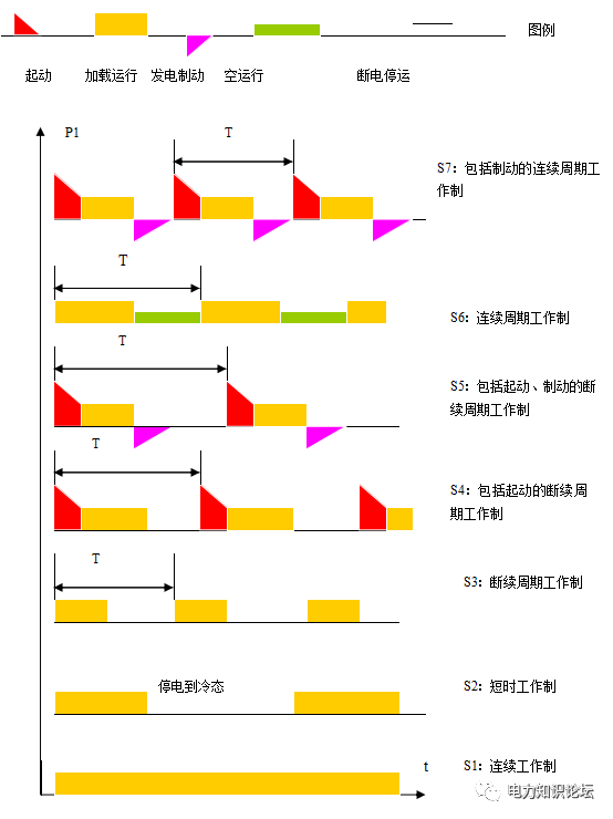
The relationship between the input power and time of the S1-S7 working system motor is given in the figure
3) S3-S8 are the concurrent working system for various situations.
4) S9 and S10 are asynchronous working system and discrete constant load working system respectively.
5) S1 working system may not be marked on the nameplate.
9. Installation method:
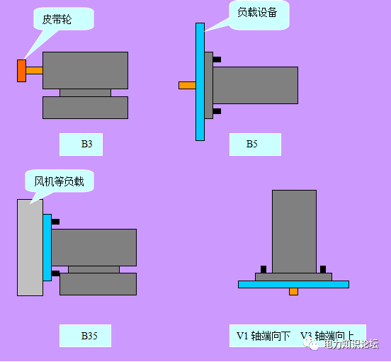
How a motor is mounted refers to how it connects to the frame or other components in the mechanical system. There are two code forms, one is IMBx and the other is IMBy. Among them, IM is an international general method, B means horizontal, and the motor is installed horizontally; V means vertical, only the motor shaft is vertical, x and y are 1-2 numbers each, indicating the connection position and direction. as the picture shows:
10. Efficiency and power factor:
1) Efficiency η=P2/P1×100%=[(P1-∑P)/P1]×100%
Among them: P2 is the shaft output power
P1 is the electrical input power
∑P is the sum of motor losses
2) Power factor
cos∮ The ratio of the active power P1 input by the motor to the apparent power S1 under load is cos∮=P1/S1. It is the power factor of the specified side, which reflects the reactive power absorbed from the grid when the motor is running. ∮ indicates the phase angle of the phase current lagging the phase voltage in the stator winding. The power factor directly affects the utilization of electrical equipment: A low power factor means that more reactive power needs to be absorbed from the grid, which will increase the burden on the grid and reduce the effective utilization of power generation equipment.
In order to make full use of the power of the motor, the phenomenon of large horses and small carts should not appear. It should be operated under rated load and rated power factor cos∮N.


 XINDA
XINDA