How can the drive motor achieve high efficiency and cost reduction?
As one of the three core components of new energy vehicles, the drive motor must continue to increase power output and continuously reduce production costs in order to effectively meet the needs of car buyers for low-cost and high-end vehicles. Only in this way will the sales of new energy vehicles continue to soar.
If the electric drive system in the vehicle is analyzed separately, the motor cost accounts for 27% of the electric drive system, the controller accounts for 60%, and the reduction mechanism accounts for 13%. It can be seen that the cost of the motor and the controller account for a large proportion, and these two components are the main cost reduction. Although the cost of the reducer is relatively small, if it cooperates well, it will get twice the result with half the effort.
This article mainly talks about the manufacturing process of the motor stator and rotor assembly.
Stator assembly and manufacturing
The stator assembly of the new energy vehicle permanent magnet synchronous motor involves components such as coils, iron cores, tooth poles and casings, as shown in Figure 1.
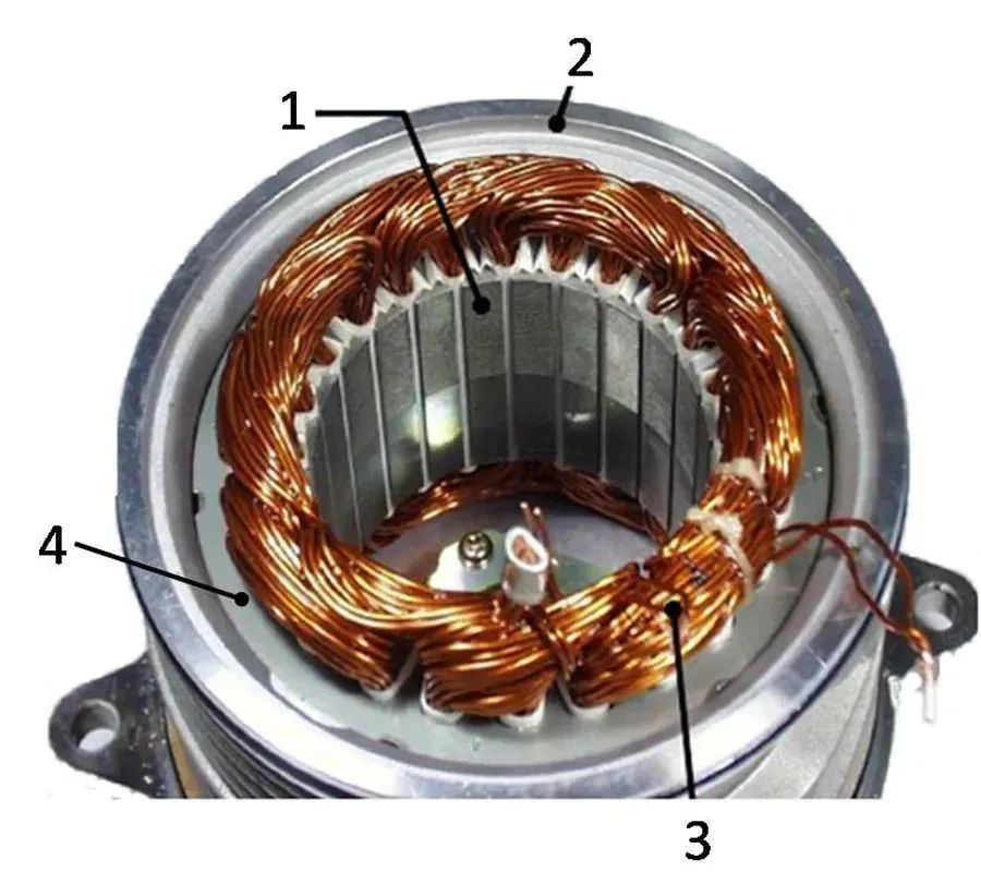
Figure 1 Schematic diagram of the stator assembly of a permanent magnet synchronous motor for a new energy vehicle
1-tooth pole 2-casing 3-coil 4-iron core
According to statistics, the stator assembly accounts for about 35% of the cost of permanent magnet motors. Moreover, the demand for personalized customization of new energy vehicles is increasing. Most of the models are in the state of small and medium batches. The permanent magnet motors equipped with them present small motors with variable structures, wide performance, urgent orders, and stator diameters ranging from 80-400mm. popularization phenomenon.
Therefore, the production of high-cost stator assemblies cannot continue to use traditional manufacturing solutions. Instead, card-issuing technology, digital technology, and information technology are used to improve the flexibility, integration, and high efficiency of the stator production line, thereby reducing space occupation, Shorten lead times and reduce production costs.
Process route of stator assembly
The usual process route of the stator assembly is shown in Figure 2. This route does not involve the machining of the inner hole of the casing and the stamping, riveting, shaping and welding of the stator core.
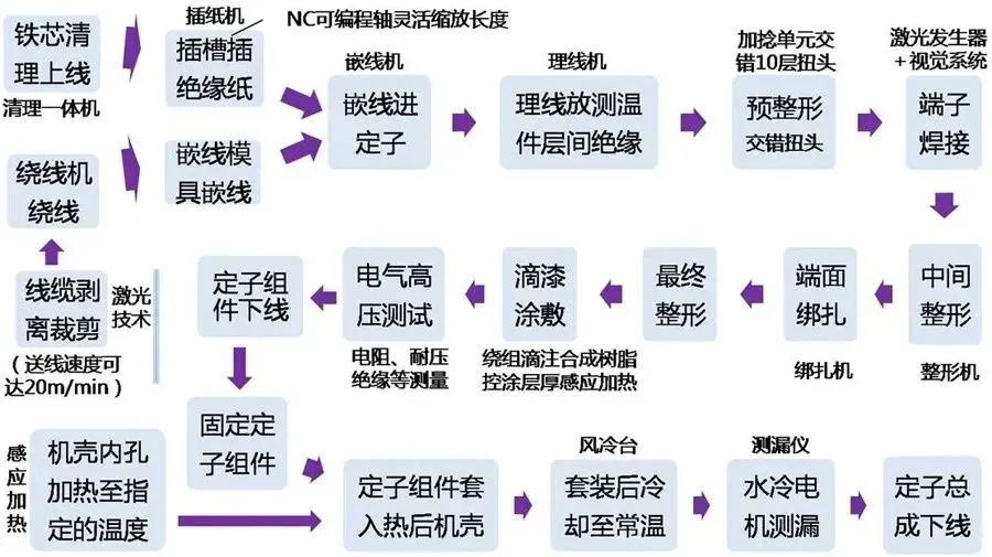
Figure 2 The usual process route of the stator assembly
Manufacture of Stator Assembly
Analysis of the usual process route of the stator assembly shows that the stator of the permanent magnet motor needs to go through two stages of component manufacturing and subsequent insertion into the inner hole of the casing before it can become a set of qualified complete assembly devices;
The equipment used involves industrial cleaning machines, thread inserting machines, thread management machines, binding machines, etc., as well as cutting machines and welding machines with laser technology, as well as paper inserting machines, heating machines, shaping machines and packaging machines for servo axis positioning. There are also flammable and explosive dipping and drying equipment, as shown in Figure 3.
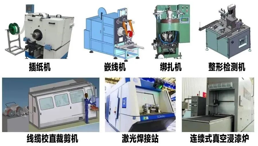
Figure 3 Schematic diagram of the equipment used in the manufacture of the stator assembly
A large number of operating equipment, a large amount of investment, a long process flow, a large floor area, slow product switching, and thin-walled subtractive processing of the casing are the salient features of the stator assembly manufacturing route.
In the era of rapidly changing personalization markets, motor manufacturers should:
-
Use robots to load and unload materials instead of a large number of manual hoisting;
-
Use AGV trolley or suspension chain to transport stator parts;
-
Use digital equipment to improve the flexibility of changeover;
-
Use the Internet to collect and analyze data such as parts information, production line status, online actual control, and order distribution;
-
Use hydraulic/pneumatic self-centering quick-change multi-station fixtures (see Figure 4) for quick clamping and loosening of material reduction parts;
-
Using the cloud platform to carry out the optimal collaborative order dispatching of component suppliers, etc.,
In this way, the cost reduction control of stator manufacturing can be realized, and the manufacture of small batches of motors can be completed quickly in a short period of time. The surface roughness and roundness do not exceed Ra1.6μm and 8μm respectively.
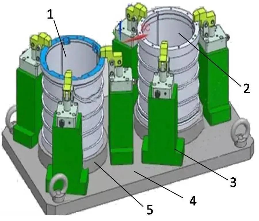
Fig. 4 Hydraulic/pneumatic self-centering for material reduction of motor casing
Quick change multi-station fixture
1. 2-Motor shell 3-Clamp loose structure 4-Clamp base 5-Positioning support
Rotor Assembly and Manufacturing
In recent years, almost all EVs and HEVs, including the Tesla Model 3, have installed an interior permanent magnet synchronous reluctance motor (IPMSynRM).
The rotor assembly of this type of motor is mainly composed of rotor shaft, rotor core, permanent magnet (also known as magnetic steel) and front and rear baffles, as shown in Figure 5.
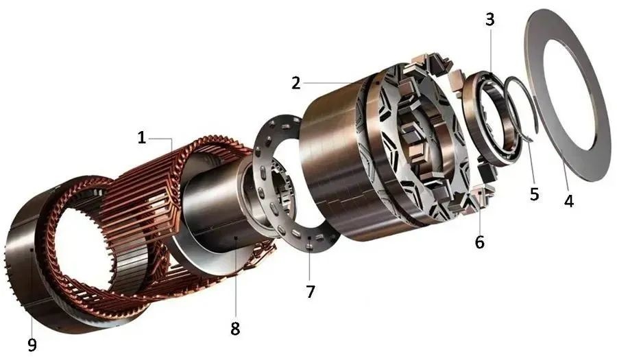
Fig.5 Schematic illustration of rotor assembly explosion of permanent magnet synchronous reluctance motor
1-hairpin stator coil 2-rotor core section 3-bearing
4-Permanent magnet front bezel 5-Stop washer 6-Permanent magnet
7-Permanent magnet tailgate 8-Rotor shaft 9-Stator core
The IPMSynRMs of different manufacturers are technically different, mainly in the size, position, shape and quantity of permanent magnets.
From principle, design to production, any small change, Tesla, BBA, Toyota, Honda and other manufacturers will conduct multi-frequency software simulation and hardware testing to form unique core intellectual property rights.
Felsomat adopts a modular intelligent manufacturing integration solution, innovates the rotor design, obtains the synthetic magnetic field map of the iron core through software, improves the angle of the iron core and the form of the permanent magnet, optimizes the process route, and performs digital cutting, automatic assembly and Data-based analysis enables the motor rotor to generate permanent magnet torque and reluctance torque through built-in permanent magnets and V-shaped slots, and finally realizes the maximum torque angle of the motor at low speed and field weakening under high-speed conditions.
Process route of rotor assembly
The usual process route of the rotor assembly is shown in Figure 6. Rotor shaft subtractive manufacturing involves turning and grinding of outer circle and steps, hobbing of splines, milling of keyways, turning and boring of inner circles, drilling, expanding, tapping and chamfering of bolt holes, etc.
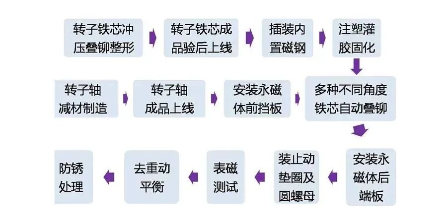
Figure 6 The usual process route of the rotor assembly
The surface magnetic test involves the detection of parameters such as the number of magnetic poles, polarity, peak value of magnetic poles, angle, area, width, and half-width height.
Manufacture of rotor assemblies
Historical data shows that in the manufacture of permanent magnet motors, raw material costs and processing costs account for the vast majority of motor costs.
Among them, the cost of permanent magnets made of rare earth materials such as NdFeB accounted for about 44.9% of the total cost, the cost of the stator core combined with steel and copper windings accounted for 17.4%, and the cost of the magnesium-aluminum alloy casing and steel rotor accounted for 12.8% respectively. vs. 7.5%.
Once the price of raw materials rises and labor costs increase, the cost of permanent magnet motors will inevitably increase, and the price of new energy vehicles will inevitably fluctuate accordingly.
Therefore, domestic motor suppliers can learn from the effective measures to reduce the cost of motors in Europe, America, Japan and South Korea, so that the motor products have the characteristics of integration, light weight, personalized durability, low price, and safety, so that the peak power density of the electric drive system And the continuous power density can be continuously doubled on the basis of 4kW/kg and 2.2kW/kg in 2020.
These measures include:
-
The rotor shaft and supporting parts are replaced by wear-resistant non-metallic materials to reduce the total weight and cost of the system;
-
Explore the application of new materials, such as cobalt films covered with buckminster fullerene molecules, to solve the problems of scarcity of rare earth resources, toxic side effects and environmental damage during mining;
-
Improve material utilization by optimizing the motor structure, such as pole-slot ratio, tooth-slot ratio, split ratio, etc.;
-
Reset the process route, remove inventory, optimize the process, save resources, eliminate internal friction, and improve efficiency;
-
Introduce metal 3D printing to replace the production line with long process, many equipment and large fixed capital;
-
Increase the coverage of automatic assembly and flexible cutting, and adopt robot operations in all links such as magnetic steel insertion, parts loading and unloading, surface magnetic testing, and plastic curing, and process parts such as rotor shafts, baffles, gaskets, end covers, and transmission bottom cases. It is completed on the automated production line (see Figure 7), and the unit cost is reduced by reducing defective waste and increasing shift output.
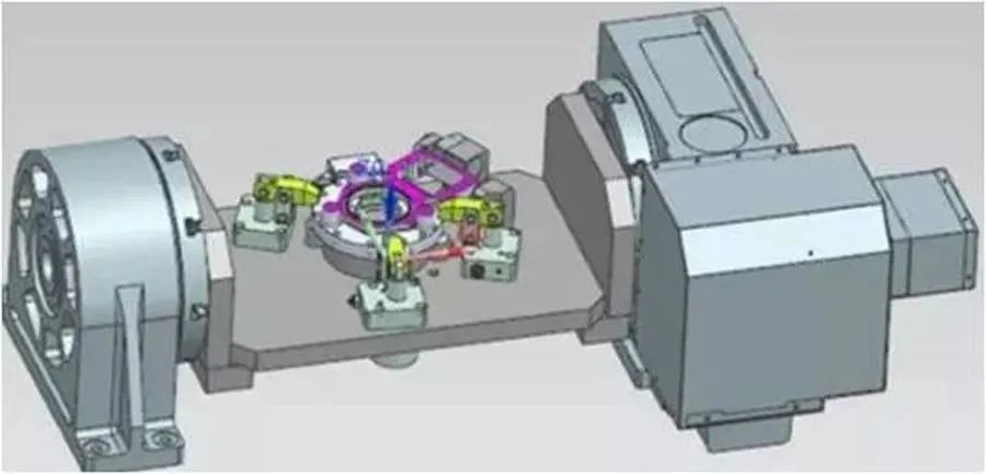
1- Motor end cover

2-Transmission bottom case
Fig.7 Schematic diagram of quick clamping of motor end cover and transmission bottom case under flexible cutting
Stator and rotor assembly test and manufacture
I believe that many CNC equipment operators have seen the unmanned manufacturing video of FANUC factory servo motor production, assembly, testing and packaging.
Through the networking of production equipment to build the Internet of Things in the workshop, the visualization of production data to make production decisions, the paperless production documents to help efficient green manufacturing, the transparency of the production process to achieve the central nervous system control, and the unmanned production site to improve production and quality, FANUC has realized Achieved a monthly production of 180,000 servo motors, accounting for 50% of the world market and 70% of the Japanese domestic market.
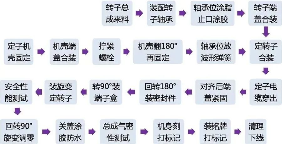
Figure 8 Reference route for combined test of stator and rotor
It is recommended that domestic motor suppliers refer to the experience of FANUC in building factories and lines, absorb its essence in efficiency, business development, personnel optimization, financial management, etc., and build an unmanned workshop for stator and rotor assembly testing (see Figure 8). Through in-depth learning, network construction, intelligence-gathering innovation, collaborative distribution, precision marketing and other means, the full-process distribution of permanent magnet motors based on three levels of operational intelligence, operational intelligence and business intelligence will be realized, so as to make great strides in the new energy vehicle market. Get a piece of the action.
Other efficiency enhancement and cost reduction schemes
JUYI power all-in-one helps break the situation
Deep integration, simplicity and integration are one of the key ways to meet the performance and cost requirements of large-scale vehicles for electric drive systems, as well as the requirements for "domain" integration of electronic and electrical architectures.
At present, OEM officials such as BYD, Changan, and GAC Aian have announced that they are applying or will soon mass-produce the all-in-one electric drive assembly. - A development or supporting process.
Both upstream and downstream enterprises agree that the deep integration technology of powertrain will go through three stages:
-
physical integration;
-
Deep integration of power domain;
-
Multi-domain highly integrated. As the level of integration increases, the potential for cost reduction and efficiency enhancement will continue to be stimulated.
Among them, Juyi Power has truly demonstrated the effect of cost reduction and efficiency increase through the development project of the all-in-one electric drive product platform and the actual vehicle test.
The technical solution in the physical integration stage is based on the six-in-one master-slave distribution architecture. According to the existing platform's component sharing strategy, the motor, electric control, and reducer share the same housing, reducing the number of connecting cables and cooling water pipes. Controllers such as MCU, DCDC, OBC, and PDU can be integrated into platform subsystems such as inverter bricks, power bricks, and power distribution bricks according to their functions, and share wiring harnesses, connectors, and housings to reduce hardware costs. Equipped with different levels of complete vehicles to reduce development costs and shorten the development cycle.
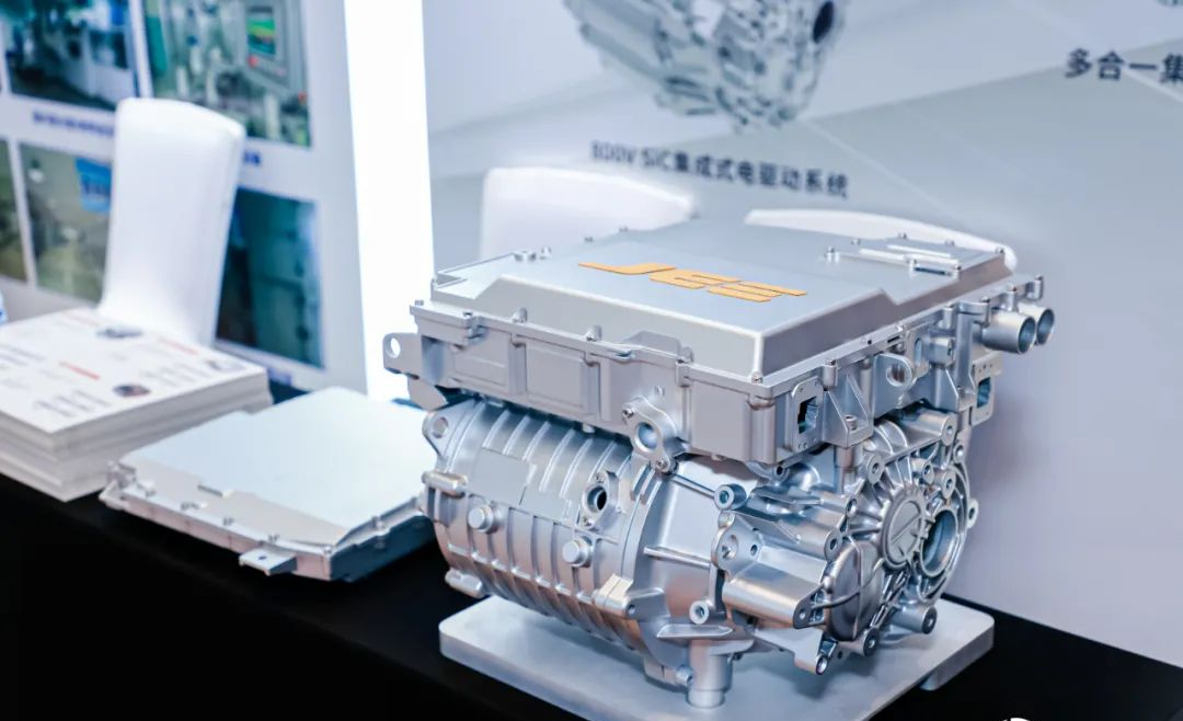
At the stage of deep integration of the power domain of the all-in-one integrated architecture, the motor, electric control and reducer adopt a common housing, common oil passage cooling, input shaft and three bearings, with a compact structure and convenient vehicle layout. The functional logic of each discrete controller is integrated with the domain controller, which further reduces the volume and weight of the controller. More importantly, the utilization rate of DSP computing power is improved, and the total demand for computing power design is reduced.
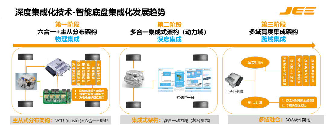
At the stage of high multi-domain integration, in-wheel motors and wheel-side motors will simplify the reducer and chassis, reduce the weight of the electric drive, and increase the cruising range. In terms of controllers, the power domain and chassis domain are integrated across domains to form a central controller. With the improvement of DSP computing power and resources, the central controller becomes the only ECU, and the cost is further reduced.
At present, Juyi Power's all-in-one electric drive assembly has passed the first stage and is heading towards the ultimate direction of the second stage. After being highly integrated, its all-in-one solution can greatly reduce costs, reduce weight and volume by 10% to 20%, increase the area of high-efficiency systems, and reduce NVH noise.
At the same time, BYD, Changan, Weimax and other electric drive upstream and downstream enterprises said that in addition to sharing hardware and software resources to reduce costs, the all-in-one solution can also simplify the development cycle, reduce development costs, and improve the driving experience.
Combining the solutions and ideas of mainstream OEMs and electric drive suppliers, the all-in-one cost reduction and efficiency increase is mainly achieved through two aspects:
-
The all-in-one solution achieves BOM cost reduction by sharing hardware such as housings, wiring harnesses, and connectors, and integrating electronic circuits and software algorithms.
-
The all-in-one solution can simplify the management of the OEM supply chain, shorten the development cycle, and achieve efficient management and cost reduction.


 XINDA
XINDA