An article explaining the efficiency of motors
Concepts and rules related to efficiency are often explained at work, so I simply dedicated a special article to clarify them from beginning to end. It targets a wide range of people, and it is troublesome to edit formulas on public accounts, so this issue is just text plus a few charts.
Efficiency is the ratio of the shaft power output by the motor to the electric power input. It is one of the important indicators for evaluating the motor. In the context of climate change and dual-carbon goals, improving efficiency is the eternal pursuit of the motor industry.
Electric power is active power, so high efficiency means energy saving. Power factor affects apparent power and has no direct relationship with energy saving.
The difference between input power and output power is loss. The smaller the loss, the higher the efficiency.
The losses of a three-phase asynchronous motor running at power frequency can usually be divided into five parts: stator copper loss, stator iron loss, rotor copper (aluminum) loss, wind and friction (mechanical) loss and stray loss.
Stator copper loss is related to stator resistance and current; stator iron loss usually includes no-load stray loss, which is related to silicon steel sheet material, lamination process, magnetic flux density and power frequency; rotor copper loss is related to the output power and slip rate of the motor Proportional; wind friction is caused by bearing friction and air resistance of rotating parts, and is related to the motor speed; stray loss generally refers to load stray loss, is proportional to the output torque, and is also related to the electromagnetic design, process method and manufacturing of the motor. related to level. Generally speaking, stator copper loss and iron loss are the main parts of motor losses.
It can be seen that when the voltage of the motor is rated after the motor is ready, the stator iron loss and wind friction loss have almost nothing to do with the load size (output power). The sum of the two is called constant loss; the stator copper loss, rotor copper loss and stray loss change with the load. Change is variable loss. Obviously, the larger the load, the greater the variable losses. A good design is that the constant loss of the motor is approximately equal to the variable loss at rated load. At this time, the motor has higher efficiency.
Improving the efficiency of the motor is nothing more than starting from the above aspects: increasing the size can not only increase the cross-sectional area of the electromagnetic wire and reduce the resistance, but also increase the amount of iron core and reduce the magnetic flux density. It can also reduce the temperature rise of the motor and use a small fan to reduce wind. Friction loss; use high-grade silicon steel sheets to reduce iron loss per unit weight of the core; use cast copper or copper bar rotors to reduce slip and reduce rotor copper loss; improve and improve the process level to reduce load stray losses.

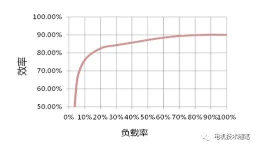
As shown in the figure above, under rated voltage and rated frequency, the relationship between the motor's efficiency and output power can be expressed by the efficiency curve. Usually the efficiency is highest near the rated load, and as the load decreases, the efficiency gradually decreases. If the rated efficiency of the motor is high enough, then the efficiency decreases slowly with the load (if the rated efficiency is 99%, then the efficiency must be greater than 98% at 50% load, and the efficiency must be greater than 90% at 10% load). Please explain the reason. Readers can make their own analysis.
In fact, motor manufacturers understand that users leave a certain margin when selecting motors, and the actual power used often does not reach the rated power. In this design, the maximum efficiency point will be set near 75% load, and the energy saving effect will be better. If the load fluctuates greatly during operation, the user may be more concerned about the average efficiency of different load points, which actually requires smaller constant losses.
For permanent magnet motors powered by power frequency, the analysis method of asynchronous motors is basically applicable, but there are two differences: first, there is no rotor copper loss (the eddy current loss of the permanent magnet is very small), and the efficiency of permanent magnet motors is higher than that of asynchronous motors after considering other factors. Quite a few; secondly, the stator iron loss and wind friction loss are not easy to separate (after a power outage, there is still iron loss in the rotor rotation, so the permanent magnet motor stops quickly).
The above analysis is about the efficiency of a single motor. Next, we will discuss the efficiency comparison between motors of different specifications when the same electromagnetic load and electromagnetic materials, similar structure and process manufacturing level are used. In order to highlight the main contradiction, we use stator copper loss and stator iron loss to represent losses.
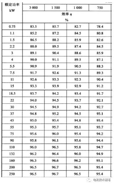
The relationship between rated power and rated efficiency. Compared with a motor with a rated power of 3kW and a motor with a rated power of 300kW, which one is more efficient? We all know it's the latter. This is because the rated power of the motor is proportional to the 4/3 power of the motor's volume, and the loss is proportional to the volume, that is, the power increases faster than the loss, so the greater the power, the higher the efficiency.
The relationship between rated speed and rated efficiency. We know that the motor constants, that is, when the voltage and power are the same, the lower the speed, the larger the motor will be. So between a 90kW motor with a rated speed of 150 rpm and a motor with a rated speed of 1,500 rpm, which one is more efficient? Because the volume of a 150-rpm motor is much larger than that of a 1,500-rpm motor, and the electromagnetic load is similar, the loss of a 150-rpm motor is also much greater than that of a 1,500-rpm motor. So the lower the speed, the lower the efficiency.
Of course, the higher the speed, the higher the efficiency. Generally speaking, the motor with a rated speed of 1500rpm has the highest efficiency. This is because the first high-speed motor inevitably increases the rated frequency, and even if the magnetic density remains unchanged, the higher the frequency, the greater the iron loss; the second, the higher the speed, the more prominent the wind and friction loss. Some readers may ask, why is the efficiency of a 2-pole motor (3000 rpm) lower than a 4-pole motor (1500 rpm) at power frequency? In addition to the greater wind friction loss at 3000 rpm, the main reason is that the material utilization rate of the 2-pole motor is low. The stator yoke area under each pole is large so the iron loss is large, and the coil end connection wire is long so the copper loss is large.
Relationship between rated voltage and rated efficiency. If the speed and power are the same, which one with a rated voltage of 380V has higher efficiency, or one with a rated voltage of 3300V? Of course, the manufacturing processes of the two motors are different, and some are not easy to compare. But I think in general, low voltage motors are more efficient. Because the higher the voltage, the more insulation materials are used, which reduces the utilization rate of electromagnetic materials and causes greater losses.
Above, let’s talk about the pictures. In the figure below, the efficiency index of the IE4 motor can be clearly seen. The rated voltage of this standard is 380/660V. Please check the efficiency standards of high-voltage motors by yourself.

Other aspects, such as protection type and cooling method, do not have much impact on efficiency and will not be discussed here.
GB18613 is a mandatory national standard that stipulates the energy efficiency limits of closed asynchronous motors powered by industrial frequency power supplies below 1000V. The standard is divided into three energy efficiency levels, with Level 1 being the highest and Level 3 being the lowest. Motors used in China must reach Level 3 energy efficiency at least.
When the motor is used for export, you can refer to IEC60034-30-1 to determine the energy efficiency level. The national standard GB32891.2 is the translated version of this standard. In fact, the efficiency index of three-phase asynchronous motors in GB18613 is the reference IEC standard. The energy efficiency levels 1, 2, and 3 in GB18613 correspond to IE5, IE4, and IE3 in IEC60034-30-1 respectively.
Others such as high-voltage motors, self-starting permanent magnet motors, pole-changing motors, short-time or periodic duty motors and other special-purpose motors have corresponding standards. Different application industries may also have their own standards. Most of these are recommended. Just clearly quote the terms to the user.
Next, we discuss the shifting situation. Variable speed here refers to variable frequency speed regulation. The application range of pole-changing speed regulation and rotor string resistance speed regulation is limited, and there is a tendency to be replaced by variable frequency speed regulation. For the sake of simplicity, let’s first discuss the change of efficiency with speed at constant torque below the rated speed.
When the speed decreases, the torque remains unchanged, and the current and magnetic density remain unchanged, but the iron loss will decrease with the 1.3 power of the frequency; whether the stator copper loss changes depends on the temperature of the stator (of course, the frequency also has some influence on the AC resistance) , if the cooling method has nothing to do with the speed, then the stator copper loss is almost unchanged; the slip of the asynchronous motor does not change much, so the rotor copper loss becomes smaller in proportion to the output power; the change in wind friction loss is closely related to the cooling method, if the motor does not The wind friction loss of the self-cooling fan is very small and can be ignored: the comprehensive evaluation shows that the efficiency decreases slowly.
Within a range above the rated speed, the motor can operate at constant power. The current of the asynchronous motor does not change much, but the stator copper loss of the permanent magnet motor will be larger, because the direct axis current needs to be increased to balance the back electromotive force; the magnetic field weakens and the slip rate increases, so the rotor copper loss of the asynchronous motor will increase; magnetized Due to the decrease in density but the increase in frequency, the iron loss will be slightly smaller; the proportion of wind friction loss is relatively small: comprehensively speaking, the motor can be in the high efficiency zone within a certain range of increase in speed.
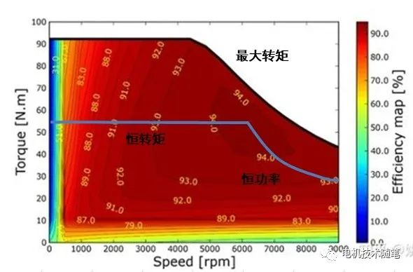
We have discussed before that the efficiency changes when the speed is constant and the load decreases. In this way, if the horizontal axis represents the speed and the vertical axis torque, the efficiency changes below the constant torque-constant power curve can be roughly clarified. The main drive motor of an electric vehicle usually has to run at overspeed and reduce power to the left of the constant power point, and also runs for a short time above the constant torque-constant power curve, up to the peak torque at each speed. Connect the points with the same efficiency in the entire operating area to form several topographic maps like altitude contours. This is the motor's efficiency MAP.

Obviously, the efficiency near the rated point should be relatively high. The closer to the coordinate axis or peak torque line, the lower the efficiency. There is a common requirement in the internal industry of "Double 85", that is, within the work area, the area with an efficiency of more than 85% must account for more than 85% of the total area. This kind of motor is highly customizable, and I haven't seen a standard with specific requirements.
In short, the efficiency curve has only one independent variable, load torque, which is a one-dimensional curve; the efficiency MAP diagram has two independent variables, torque and speed, which is a two-dimensional plane.
Above, the impact of the inverter power supply has not been considered. As we all know, the power supply voltage of the frequency converter is a high-pulse rectangular wave, not an ideal sine wave. Therefore, compared with the power supply of industrial frequency power supply, the loss of the motor will increase, and the increased loss is called additional harmonic loss. The size of the additional harmonic loss is related to the settings of the frequency converter. According to the recommendations of IEC60034-30-2 (corresponding to the national standard GB32891.2), if the rated frequency of the motor is 50Hz or 60Hz and the inverter is two-level, the additional harmonic loss is 15% (switching frequency 4K) or 25% of the basic loss (Switching frequency 2K). For specific calculation methods, please refer to the previously written "The Impact of Frequency Converter Carrier Frequency on Motor Efficiency".
In fact, the components of additional harmonic loss are very complex, and their impact on the motor is multifaceted. The specific calculation is beyond the scope of this article, and several papers can be published. In short, the higher the carrier frequency ratio of the inverter, the closer the voltage waveform is to a sine wave and the smaller the additional harmonic loss. If the rotational speed increases and the carrier frequency remains unchanged, the additional harmonic loss in the high-frequency area will be larger. This loss can also be reduced from the perspective of motor design, which is a hot topic of research now.
The energy efficiency standard for variable speed motors is the IEC60034-30-2 just mentioned, which corresponds to the national standard GB32891.2. It should be pointed out that the IEC60034-30 series of standards covers a wider range. It includes not only asynchronous motors, but also permanent magnet motors and reluctance motors. In summary, it is an AC motor; and regardless of the motor type, the power and speed will be corresponding after a certain Level efficiency indicators. GB18613 mainly covers asynchronous motors and brushless DC motors for specific use occasions, and different motor types have different corresponding energy efficiency indicators. Other specific contents will not be introduced one by one.


 XINDA
XINDA