![]()
When the three-phase stator windings of the motor (each phase difference is 120 degrees in electrical angle), after the three-phase symmetrical alternating current is applied, a rotating magnetic field will be generated, and the rotating magnetic field will cut the rotor winding.
As a result, an induced current is generated in the rotor winding (the rotor winding is a closed path), and the current-carrying rotor conductor will generate electromagnetic force under the action of the rotating magnetic field of the stator, thereby forming an electromagnetic torque on the motor shaft, driving the motor to rotate, and the direction of the motor rotation Same direction as the rotating magnetic field.Squirrel-cage rotor: The rotor winding consists of a plurality of bars inserted into the rotor slots and two circular end rings. If the rotor core is removed, the entire winding looks like a squirrel cage, so it is called cage winding. Small cage motors use cast aluminum rotor windings, and copper bars and copper end rings are welded for motors above 100KW.Squirrel-cage rotors are divided into: impedance rotor, single-squirrel-cage rotor, double-squirrel-cage rotor, and deep-slot rotor, with different characteristics such as starting torque.
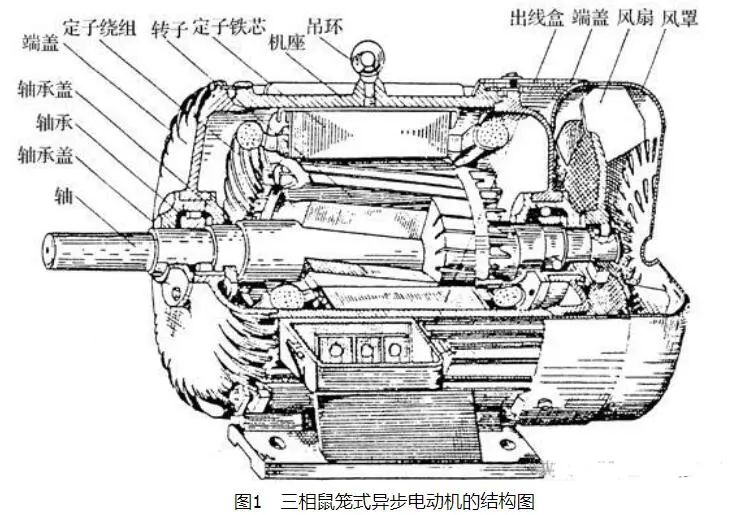
Structural diagram of three-phase squirrel-cage asynchronous motor
The main structure of the asynchronous motor is composed of two parts, the stator and the rotor, and there is an air gap between the stator and the rotor. In addition, there are end covers, bearings, machine bases and other components. Figure 1 is a structural diagram of a three-phase squirrel-cage asynchronous motor.
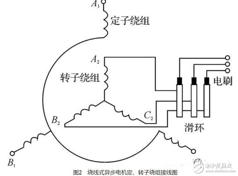
The stator is the fixed part of the asynchronous motor. It consists of machine base, stator core and stator winding.The frame is the shell of the motor, which plays a role in supporting the motor and is usually made of cast iron. The large machine base is also tailor-welded with steel plates.The stator core is part of the magnetic circuit of the motor and is installed inside the frame. It is a hollow cylinder, the outer wall is matched with the machine base, the inner wall is slotted, and the stator winding is placed in the slot. In order to reduce the loss in the iron core, the stator iron core is stacked with 0.5mm thick silicon steel sheets.The stator windings of three-phase asynchronous motors are not all connected in star connection, and only in the case of large capacity and high voltage, they are connected in star connection. Generally, for asynchronous motors with medium and small capacity and low voltage, the six wire ends of the three-phase winding are usually drawn out, and connected to the outside as a delta or star connection as required. In this way, the motor can be applied to two different levels of power supply voltage, for example, the star connection method is used for 380V power supply; When using the method, it is used for 380V power supply. When starting, it is changed to a star connection method to achieve the purpose of step-down starting.The stator winding is wound with insulated copper wire, embedded in the stator slot, and the winding is separated from the slot wall by insulating material.The air gap of an asynchronous motor is much smaller than that of a DC motor with the same capacity, and in medium and small asynchronous motors, it is generally 0.2 to 1.0mm. This is because the excitation current of the asynchronous motor is supplied by the power grid. When the air gap is large, the excitation current is also large, thereby reducing the power factor of the motor . In order to improve the power factor, the air gap should be made as small as possible. However, if the air gap is too small, assembly will be difficult, operation will be unreliable, and the high-order harmonic magnetic field will be enhanced, thereby increasing additional loss.The rotor of the motor is composed of the rotor core, the rotor winding and the shaft. The rotor iron core is also a part of the magnetic circuit, generally made of silicon steel sheets, and the iron core is fixed on the shaft.If the rotor winding is wound, it can be connected in star or delta. Generally, the small capacity is connected into a triangle; the medium and large capacity are connected into a star. The three lead-out wires of the winding are connected to three collector rings (the collector rings are fixed on the rotating shaft), and are drawn out with a set of brushes, as shown in Figure 2.
This allows an external resistor to be connected to the rotor winding loop. The purpose of series resistance is to improve the characteristics of the motor or to adjust the speed.
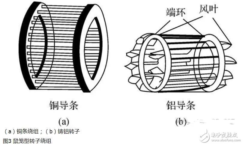
The structure of the squirrel-cage rotor winding is quite different from that of the stator winding. There are also slots on the rotor core, and there is a guide bar in each slot. There are two Swiss rings at both ends of the iron core, which respectively connect all the parts of the guide bars protruding from the groove to form a short circuit. If the rotor core is removed, the windings are shaped like a mouse cage, as shown in Figure 3(a). The material of the guide bar is copper or aluminum. If it is made of copper, it is to insert the pre-made bare copper strips into the rotor core slot, and then use copper rings to cover the heads of the copper strips at both ends, and weld them together; if it is made of aluminum windings, it is The melted aluminum liquid is directly cast in the rotor core slot, together with the ring and the fan blades, as shown in Figure 3(b).


 XINDA
XINDA