


A New Oriented Steel Laminated Rotor Core for Synchronous Reluctance Traction Motor
Technological advancements are driving the global electrification process, so choosing the right motor for your powertrain is critical. Especially in the electric vehicle industry, the need to choose electric motors with higher performance and lower cost is growing rapidly.
The anisotropy of the rotor in synchronous reluctance motors (SynRM) helps reduce the use of expensive rare-earth permanent magnets and copper or aluminum bars. Therefore, compared with permanent magnets (PMSM) and induction motors (IM), synchronous motors may provide higher cost performance and become a strong potential market for future traction motor electrification powertrains.
For the design of high-performance SynRM, it is often desired to obtain high Ld or low Lq indicators to the greatest extent. At the same time, due to the high-speed characteristics of electric vehicles, researching new rotor structures and geometries can achieve mechanically robust operation.
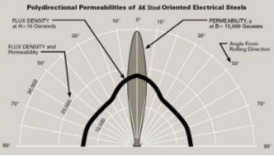
Cold-rolled grain-oriented steel (CRGO) is a product processed under strict process control, with suitable magnetic properties in the rolling direction and a very high packing factor. Therefore, when used as a core material in a design in which the magnetic flux path is parallel to the rolling direction, CRGO will obtain high high magnetic induction at low excitation current, and its normal working magnetic induction is sufficiently lower than the magnetic saturation of the material. This high magnetic induction and high stacking factor performance can provide a more compact design of the motor core, helping to reduce size and weight.
IEEE researcher Taghavi et al. proposed a new rotor pole assembly for 4-pole synchronous motors fabricated using CRGO to increase torque density for traction motors. This research work is also part of NSERC's "Design and Performance of Special Electric Motors" industrial research project.
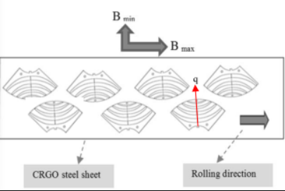
The researchers cut the CRGO steel plate into a single-stage rotor lamination shape as shown in Figure 2, so that the magnetic flux carrier of each single-pole rotor lamination can be aligned in the rolling direction, so that the direction of the q-axis is perpendicular to the rolling direction. direction.
According to this standard, both ends of any given insulation barrier of a unipolar rotor lamination are positioned parallel to the direction of rolling. In addition, the cutting layout of the monopole rotor laminations reduces the material loss of the steel plate during the cutting process. This is achieved by using a staggered cutting pattern with minimal material waste.
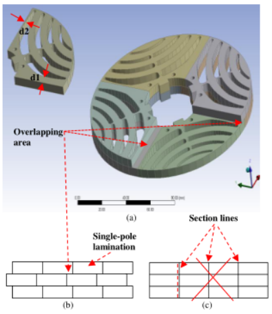
The asymmetric geometry of the single pole laminations shown in Figure 3 is the key to proper bonding of the rotor laminations. In this way, in each unipolar rotor lamination, the width of the first flux carrier on one side (d1) is designed to be much thicker than on the other side (d2), while the geometry of the barrier is relative to q Axisymmetric. The laminate assembly consists of four segmented rods starting from the placement of the first layer.
The second layer is placed on top of the first layer while each monopolar lamination is flipped substantially 180° about the q-axis, and this arrangement is repeated until the last layer. Thus during the bonding process an overlapping pattern similar to a transformer core can be achieved between two successive layers. The overlapping areas allow each single pole lamination to be connected to two other single pole laminations at the top and bottom, thus achieving a complete connection between all single pole laminations across the entire rotor lamination.
However, in the absence of overlap, each single pole lamination is connected to only one upper and one lower pole lamination, and four hatching lines are preserved throughout the rotor laminations, which reduces the mechanical integrity. After inserting epoxy material between the layers and going through a two-hour heat-pressing process, the rotor lamination is complete.
To provide proper mechanical integrity and robustness to the finished rotor, the rotor single pole laminations are clamped together using bonding techniques. For this, an epoxy bonding material is used between the layers. Each rotor pole lamination includes bolt holes and guide pins to provide proper alignment guidance during the clamping process, and at the proper temperature, the two end plates are fitted by press-fit technology to complete the rotor lamination assembly.
With this innovative rotor core design using cold-rolled grain-oriented (CRGO) electrical steel and the assembly of fabricated motor cores, experimental results show that: compared to isotropic steel (CRNGO), equipped with segments made of CRGO Pole rotor machines exhibit higher d-axis induction and lower q-axis induction at the same operating point.
Therefore, the use of oriented materials in the rotor core increases the motor saliency ratio, amplifies the output torque, and reduces the motor size at the same operating load, which is desirable for automotive applications.
In addition, the researchers proposed a geometric approach based on the rotor and stator slot helix angles to reduce the torque ripple. Mathematically express the proper slot pitch angle for the rotor to achieve lower torque ripple.
 XINDA
XINDA