The structure and working principle of DC motor
1. Nameplate data and main series of DC motors:
1. Nameplate data for DC motors:
According to the national standard, the motor manufacturer stipulates the normal operating state and conditions of the motor according to the design and test data of the motor, which is usually called the rated operating condition. All kinds of data that characterize the rated operation of the motor are called rated values. The rated value is generally marked on the nameplate of the motor, so it is also called nameplate data, which is the basis for correct and reasonable use of the motor.
Second, the basic working principle of DC motor:
DC motors are divided into two categories: DC motors and DC generators, and their working principles can be explained by a simplified model of DC motors.
1. The working principle of DC generator:
Figure 1.1 shows a simplified model of a DC generator.
In the figure , N and S are the fixed stator poles, abcd is the rotor coil fixed on the rotatable magnetically permeable cylinder, the first end a and the end d of the coil are connected to two conductive poles which are insulated from each other and can rotate together with the coil. commutation piece. The connection between the rotor coil and the external circuit is realized by a fixed brush placed on the commutator. There is a gap between the stator and the rotor, which is called the air gap:
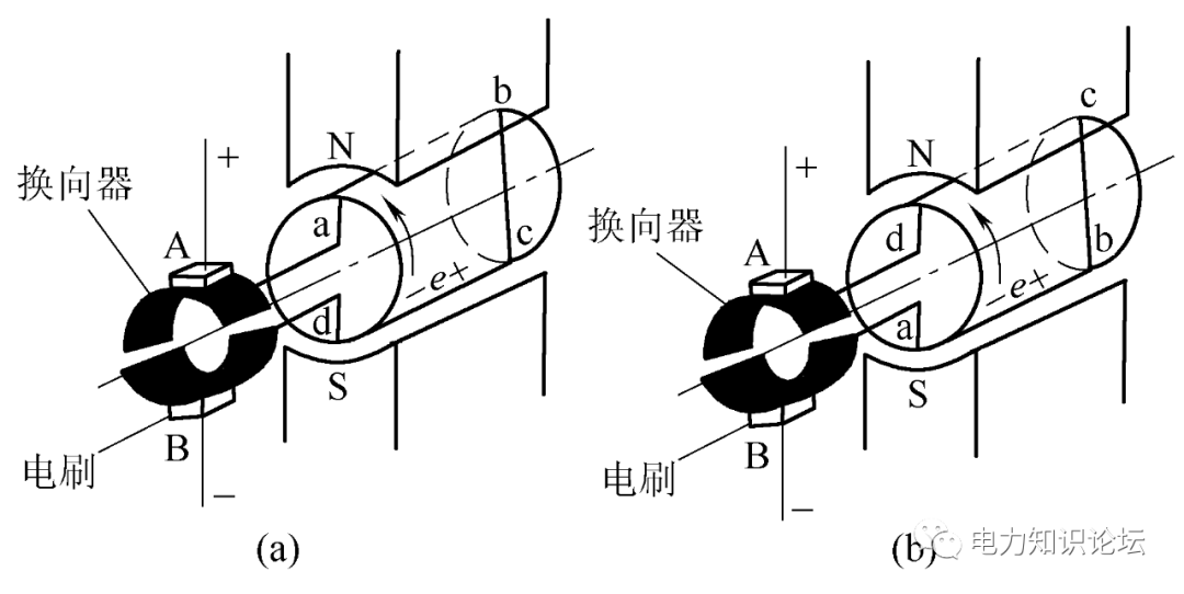
Figure 1.1 DC generator model
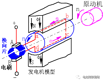
The prime mover drags the rotor to rotate
When the prime mover drives the rotor to rotate counterclockwise at a certain speed, according to Faraday's law of electromagnetic induction - the principle of the generator, it can be known that an induced electromotive force will be generated in the coil abcd that cuts the magnetic field. The magnitude of the induced electromotive force generated by the two effective side conductors should be ;
e = Bx lv ( 1-1 )
If Bx , l , v are perpendicular to each other in space, then the size of e is equal to the product of the three, and the direction of the induced electromotive force is determined by the right-hand rule.
In the formula, Bx is the magnetic flux density at the place where the conductor is located, and the unit is Wb/mm ; L is the effective length of the conductor ab or cd , and the unit is m ; v is the relative linear velocity between the conductor ab or cd and Bx , and the unit is m/mm s ; e is the electromotive force induced by the conductor, the unit is V.
2. Working principle of DC motor:
If brushes A and B are connected to a DC power supply, brush A is connected to the positive pole of the power supply, and brush B is connected to the negative pole of the power supply, at this time there will be current flowing in the armature coil.
A simplified model of a DC motor is shown in Figure 1.2(a):
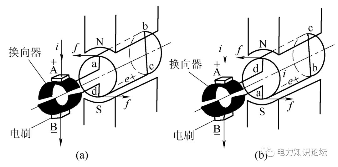
Figure 1.2 Model of a DC motor
DC motor
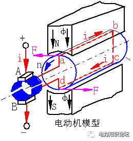
The ab side of the coil located under the N pole and the cd side of the coil located under the S pole pass through a direct current i. According to Ampere's law of electromagnetic force - the principle of the motor, the magnitude of the electromagnetic force F generated in the conductor should be:
F=Bx li (1-2)
If B and i are perpendicular to each other in space, then the size of F is equal to the product of the three, and the direction is determined by the left-hand rule. is the magnetic flux density where the conductor is located, the unit is Wb/mm; L is the effective length of the conductor ab or cd, the unit is m; i is the current flowing through the conductor, the unit is A; F is the electromagnetic force, the unit is N.
In the case of Figure 1.2(a), the force direction of the conductor ab under the N pole is from right to left, and the force direction of the conductor cd under the S pole is from left to right. The product of the electromagnetic force and the radius of the rotor is the electromagnetic torque, and the direction of the torque is counterclockwise. When the electromagnetic torque is greater than the resistance torque, the coil rotates counterclockwise.
When the armature rotates to the position shown in Figure 1.2(b), the conductor cd originally located under the S pole turns to the N pole, and its force direction changes from right to left; while the conductor ab originally located under the N pole turns Under the S pole, the force direction of the conductor ab changes from left to right, the direction of the torque is still counterclockwise, and the coil continues to rotate counterclockwise under the action of this torque.
In this way, although the current flowing in the conductor is alternating, the direction of the force on the conductor under the N pole and the direction of the force on the conductor under the S pole does not change, and the motor rotates under the action of the torque in this direction. The function of the brush is to convert the direct current into an alternating current in the coil.
The direction of the electromagnetic force F is determined by two factors; 1, the direction of the current in the conductor, and 2, the polarity of the air gap magnetic field. Changing one of them can change the direction of the electromagnetic force F.
The same DC motor can be used as a generator or as a motor. The key lies in the nature of the input power. The generator principle and the motor principle always appear at the same time, that is, the electromagnetic interaction, the armature electromotive force and the electromagnetic torque are exist at the same time.
Generator: After the load is put on, the current generated in the conductor element interacts with the magnetic field while the electric power is being output, and electromagnetic torque is generated according to the electromagnetic force theorem. Torque, the prime mover must input a large enough drag torque to overcome the braking torque, stabilize the generator speed, and realize the conversion of mechanical energy into electrical energy output.
Motor: Output mechanical power on the shaft and the conductor element moves under the main pole. According to the electromagnetic induction theorem, electromotive force is generated. Its direction is opposite to the current direction and hinders the current input. It is counter electromotive force. into the motor to realize the conversion of electrical energy into mechanical energy output.

3. Basic structure of DC motor:
The DC motor is composed of two parts: the stator (fixed) and the rotor (rotating). There is a gap between the stator and the rotor, which is called the air gap.
The stator part includes machine base, main magnetic pole, commutation pole, end cover, brush and other devices;
The rotor part includes armature core, armature winding, commutator, shaft, fan and other components.
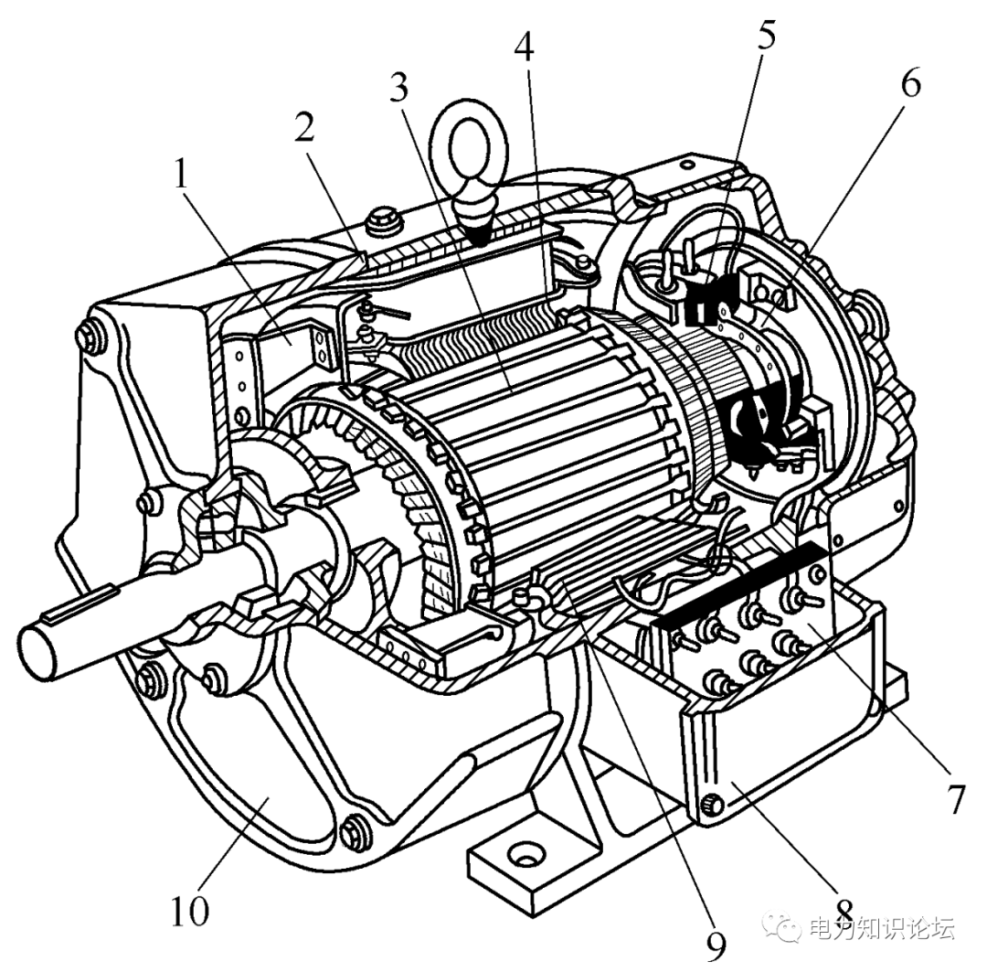
Figure 1.3 Structural diagram of a DC motor
1- fan; 2- frame; 3- armature; 4- main magnetic pole ; 5- brush holder; 6- commutator ; 7- terminal board ; 8 - outlet box ;
1. Stator part:
(1) Frame:
The base can not only fix the main magnetic pole, commutation pole, end cover, etc., but also is a part of the magnetic circuit of the motor (called the yoke). The base is generally welded with cast steel or thick steel plate, which has good magnetic permeability and mechanical strength.
( 2 ) Main pole:
The function of the main pole is to generate the air gap magnetic field, which is composed of the main pole core and the main pole winding (excitation winding).
As shown in Figure 1.4. The main pole core is generally made of 1.0mm~1.5mm thick low-carbon steel sheet laminated, including pole body and pole shoe. The pole shoe is made into an arc shape to make the air gap magnetic flux under the magnetic pole more uniform. The pole body is covered with an excitation winding,
A direct current is passed through the winding. The whole magnetic pole is fixed on the base with screws
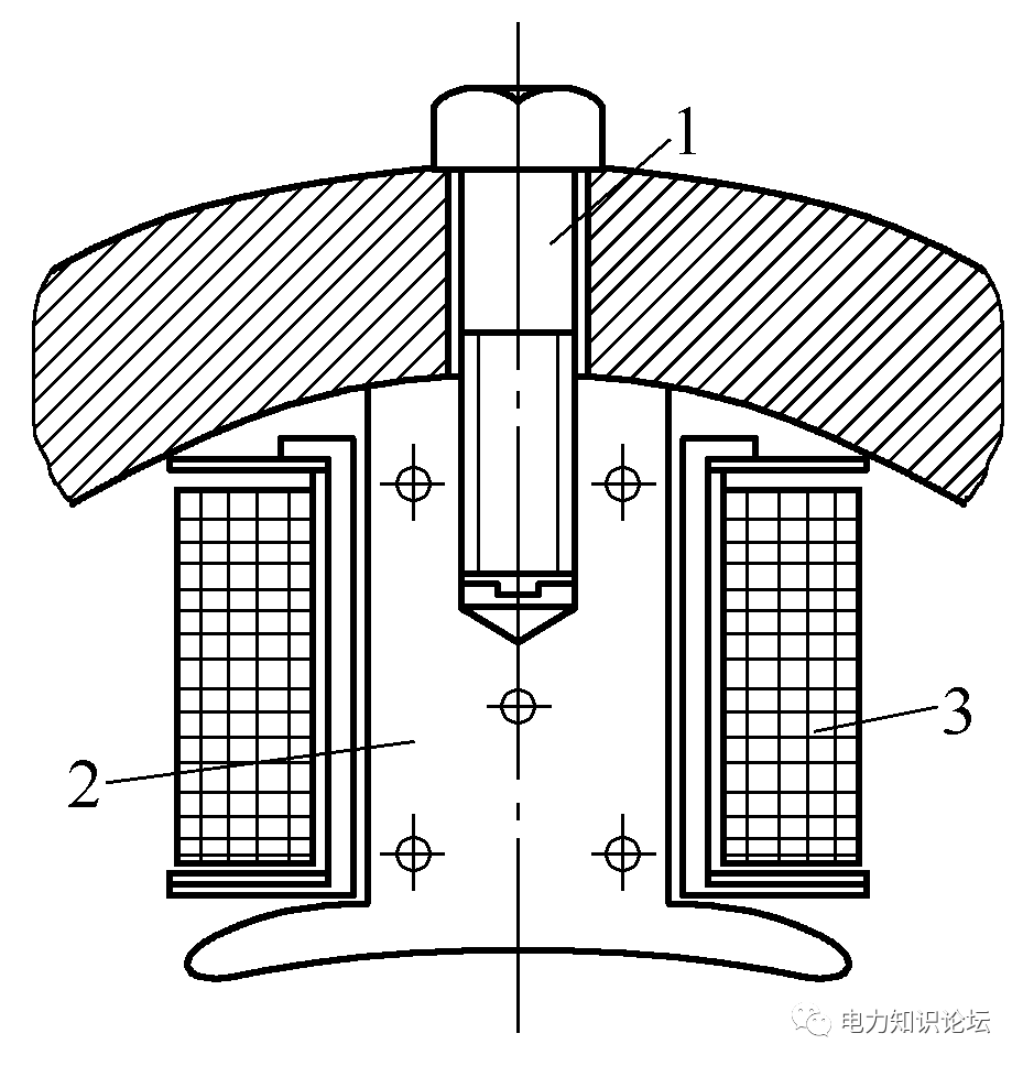
Figure 1.4 Main poles of a DC motor
1--Screw for fixing the main magnetic pole; 2- Main magnetic pole core; 3- Excitation winding
( 3 ) Commutation pole:
The commutation pole is used to improve the commutation and consists of an iron core and a winding on the iron core.
As shown in Figure 1.5. The commutation pole core is generally made of a whole piece of steel. If the commutation requirement is high, it is made of laminated steel plates with a thickness of 1.0mm to 1.5mm, and the armature current flows through the winding. The commutation pole is installed between two adjacent main poles and fixed on the base with screws.
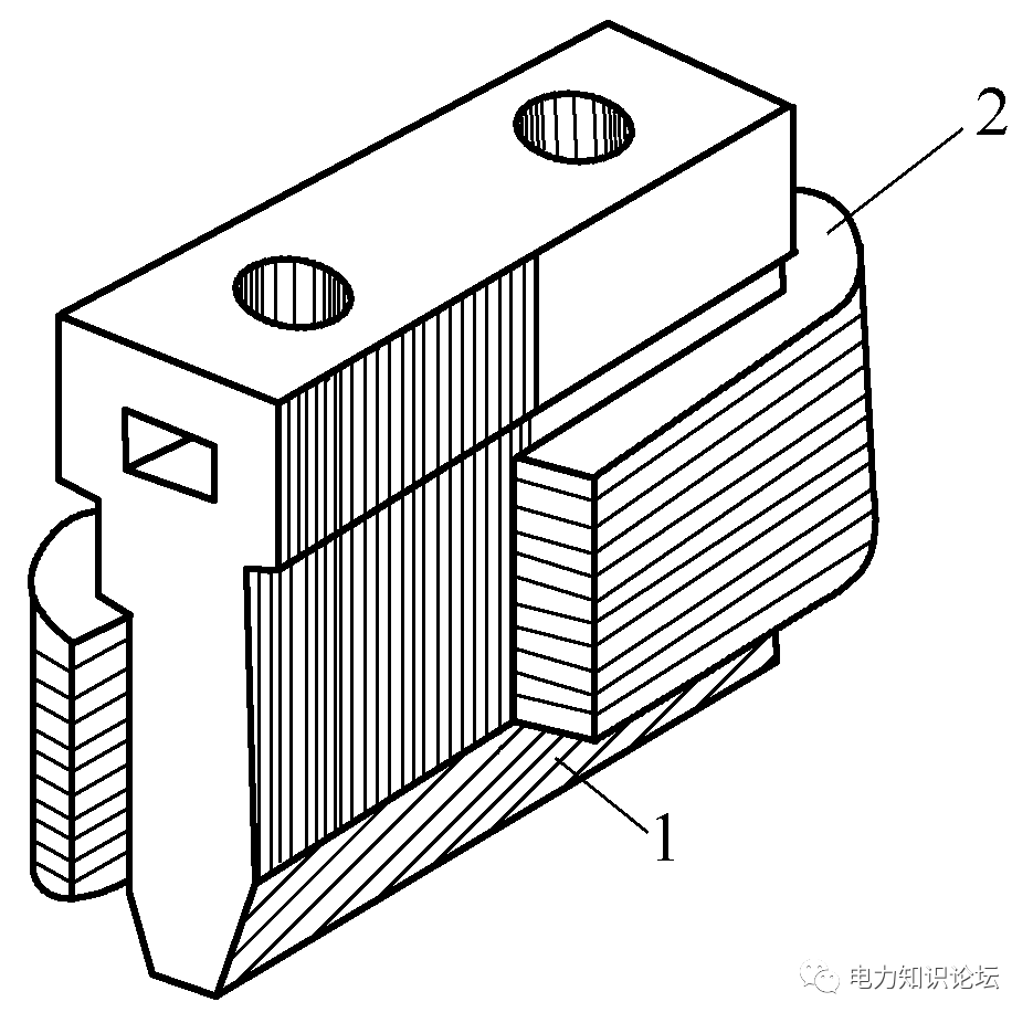
Figure 1.5 Commutation poles of a DC motor
1— commutation pole core; 2— commutation pole winding
( 4 ) Brush device:
The brush and the commutator can connect the rotating armature winding circuit with the external circuit and convert the alternating current in the armature winding into the direct current at the brush end. The brush device is composed of brushes, brush holders, brush rods, brush rod holders, springs, and copper braids, as shown in Figure 1.6. The number of brush groups is generally equal to the number of main magnetic poles.
Figure 1.6 Brush arrangement of DC motor
1— electric brush; 2— brush holder; 3— spring pressure plate; 4— seat ring 5— brush rod
There should be good contact between the brush and the working surface of the commutator. The normal brush pressure is 0.15-0.25 kg/cm2 (±10%) (measured by a spring scale). The cooperation between the brush and the brush holder frame should not be too tight. A gap of not more than 0.15mm must be left.
When the brush is worn or broken, it must be replaced with a brush of the same specification (brand and size). After the new brush is assembled, it should be ground and smoothed to achieve a consistent contact surface with the commutator.
To grind the contact surface of the brush, use No. 0 emery cloth. The width of the emery cloth is the length of the commutator, and the length of the emery cloth is the circumference of the commutator. Then find a piece of rubber glue, and half of the rubber glue sticks to one end of the emery cloth. Stick the other half of the rubber on the commutator according to the direction of rotation of the rotor, and then turn the rotor. Using this method to grind the brush, the general contact surface can reach more than 90%.
2. Rotor part:
( 1 ) Armature core:
The armature core is a part of the magnetic circuit of the motor, and its outer circumference is slotted for embedding the armature winding. The armature core is generally laminated with silicon steel sheets with a thickness of 0.5 mm and coated with insulating paint on both sides.
As shown in Figure 1.7. The armature core is fixed on the shaft or rotor bracket. When the iron core is long, in order to enhance cooling, the armature core can be divided into several sections along the axial direction, and ventilation holes are left between the sections.
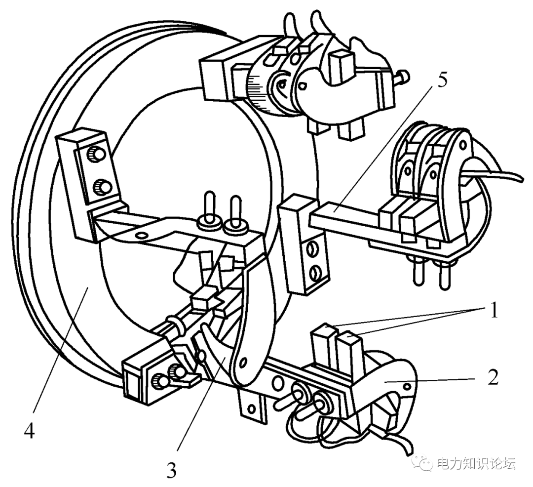
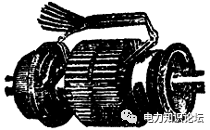
Figure 1.7 Armature core
( 2) Commutator (commutator): The commutator is a special device for DC motors:
Its appearance is shown in Figure 1-8, and it is mainly composed of many commutation segments, and the middle of every two adjacent commutation segments is an insulating sheet. On the surface of the commutator, a spring is used to press the fixed brush, so that the rotating armature winding can be connected with the external circuit. The commutator is a structural feature of a DC motor.
The surface of the commutator is very clean, and there must be no mechanical damage or spark burn marks. If there is a slight burning mark, use a No. 00 noisy cloth to grind it finely on the rotating commutator. If the surface of the commutator has severe burning marks or roughness, the surface is not round or has local unevenness, the armature should be removed for heavy driving.
It is usually required that the surface and smoothness of the commutator reach ▽6-▽7, the smoother the better. When turning, the speed should be no less than 1.5 m/s, and the cutting depth of the last cut should be no more than 0.1 mm to remove chips, burrs and other sundries on the surface of the commutator, and finally blow off the entire armature for assembly. After the commutator operates under load for a long time, a hard dark brown film will be formed on the surface. This film can protect the commutator from abrasion, so this film should be preserved and should not be worn off.
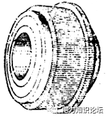

Figure 1-8 commutator


 XINDA
XINDA