The working principle and structure of the generator
1. The basic principle of the generator:
We know that cutting the magnetic lines of force by wires can generate an induced potential, and connecting the wires into a closed loop will allow current to flow. The generator works based on this principle.
Figure 1-1 shows the simplest two-pole synchronous generator. There are three-phase symmetrical windings of AX, BY, and CZ on the stator, and the rotor is the main magnetic pole of DC excitation.
When the excitation winding on the rotor magnetic pole is supplied with DC excitation current, the rotor forms the main magnetic pole magnetic field of N and S poles, and the magnetic flux Φ0 comes out from the N pole, passes through the air gap-stator core-air gap, and enters the S pole to form a magnetic field. circuit, as shown by the dotted line in the figure.
If the generator rotor is driven by the prime mover to rotate counterclockwise at speed n, the main pole magnetic flux Φ0 cuts the stator winding and induces a symmetrical three-phase potential, and the potential frequency is
In the formula: n-rotor speed, P-number of pole pairs
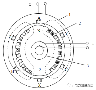
Figure 1-1 two-pole synchronous generator: 1-stator core 2- rotor 3- collector ring
The effective value of the winding potential of each phase of the stator is:
In the formula, W - turns of each phase winding, Kw - potential winding coefficient W, - magnetic flux per pole (Wb)
The waveform of the winding potential of each phase depends on the distribution of the air gap magnetic density along the circumference and the specific structure of the stator winding. For synchronous generators used in power systems, the line potential waveforms have good sinusoidal properties. However, due to the existence of high-order harmonics, the actual line potential waveform has a certain deviation from the sinusoidal waveform. As long as the amplitude of the high-order harmonics is limited within the specified range, the line potential can be considered as a sinusoidal waveform.
When the generator is loaded, current will be generated in the three-phase stator winding, and the three-phase current will generate a synthetic rotating magnetic field, which rotates at the same speed and direction as the rotor, which is called "synchronization".
2. The structure of the generator:
The motor body is mainly composed of a stationary stator (including machine base, end cover, stator core, stator winding, vibration isolation structure and end structure, etc.) and a rotatable rotor (including rotor core, rotor winding, rotor shield ring, rotor damping structure, rotor fan, etc.). In addition, in order to ensure that the stator and rotor parts of the generator do not overheat during operation, the generator is also equipped with a stator internal cooling water cooling system, a generator hydrogen cooling system and a sealing oil system to prevent hydrogen from leaking from the shaft seal.
1: generator stator
The generator stator is mainly composed of machine base, end cover, stator core, stator winding, vibration isolation structure and end structure.
1) Frame and end cover
The base is a shell structure welded by steel plates, and its main function is to support and fix the stator core and stator winding. In addition, the frame can prevent hydrogen leakage and withstand the explosive force of hydrogen.
The space between the casing and the stator core is part of the generator ventilation (hydrogen) system. Since the stator of the generator adopts axial ventilation, the hydrogen passes through the outside and inside of the iron core alternately, and then gathers and passes through the cooler, thereby effectively preventing thermal stress and local overheating.
The end cover is an integral part of the generator seal, and its structure is shown in Figure 1-9. In order to facilitate installation, maintenance and disassembly, the end cover is composed of upper and lower halves separated horizontally, and end cover bearings are provided. There is also a sealing groove on the joint surface of the end cover, and the groove is filled with sealant to ensure good airtightness.
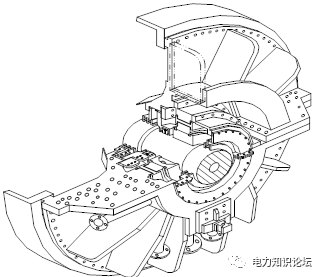
Figure 1-9 Structural drawing of generator end cover bearing
The bearing pad adopts an elliptical horizontal split surface structure, and the spherical shape of the outer circle of the bearing pad ensures that the bearing has the function of self-aligning. The hydrogen seal where the shaft passes through the end cover is guaranteed by the oil film of the oil seal. The sealing tile is made of copper alloy, there is a gap between the inner circle and the shaft, and it is installed in the sealing seat at the inner circle of the end cover. The sealing shoe is divided into four pieces, which are clamped by clamping springs in the radial direction and axial direction. Although the sealing shoe can float with the shaft in the radial direction, there are pins on the upper and lower sides of the sealing seat to prevent it from rotating tangentially. The sealing oil flows into the gap between the bearing and the shaft through the seal seat and the oil cavity of the sealing shoe to form an oil film in the radial direction to prevent hydrogen leakage. The oil seal at the excitation end is provided with double-layer insulation to prevent the shaft from being burned by the shaft current.
2) Stator core
The stator core is an important part that constitutes the magnetic circuit of the generator and fixes the stator winding. In order to reduce the magnetic hysteresis and eddy current loss of the iron core, the stator iron core is made of high-quality cold-rolled silicon steel sheet with a thickness of 0.5mm and high magnetic permeability. Each layer of silicon steel sheet is composed of several fan-shaped sheets to form a circle, and each fan-shaped sheet is coated with high-temperature resistant water-soluble inorganic insulating paint. The axial fixed structure of the stator core adopts insulated core-through screw, segmented tooth pressure plate and integral pressure plate compression structure; the natural vibration frequency avoids the fundamental frequency and multiplied frequency by more than ±10%, and the amplitude is less than 50μm; the pressure finger at the end of the iron core 1. The pressure plate is made of non-magnetic material; the outside of the pressure plate is equipped with magnetic shielding.
3) Stator winding
The stator winding is a fractional pole-pitch double-layer winding composed of bar-shaped bars, which are embedded in rectangular slots evenly distributed along the circumference of the entire stator core. A wire bar is divided into a straight part and two terminal parts. The straight part is placed in the groove, which is the effective side for cutting the induced electromotive force of the magnetic force line, and the end wires are regularly connected according to the winding connection pattern.
There are 84 stator bars, which are composed of stainless steel water pipes and solid copper wires; solid oxygen-free copper wires are covered with insulation; the upper and lower layers of bars are of equal cross-section; the bars are double-row structure, and each row is separated by 5 and 1 space. Stack 5 groups; in order to reduce the self-induced eddy current loss generated by the stator winding under load operating conditions, the wires of the straight part of the stator bar are braided with 540° empty transposition. The so-called transposition means that when weaving the wire rods, let each wire rod be located at different heights in the groove along the axial length, so that the leakage reactance of each wire rod is equal, so that the current in each conductor is uniform, reducing the linear and The circulating current and additional loss generated by the transverse leakage flux at the end in each conductor.
All the strands at the ends of the stator bars are welded to the water and electricity joints, and the two wire bars are welded together through the copper strips to form an electrical connection, forming a coil; while the cooling water in all the hollow strands passes through the water and electricity joints The water path of the coil is connected to the confluence main pipe near the excitation end, and enters the coil through the insulated water diversion pipe. A jellyfish inlet pipe is arranged at the generator end; a jellyfish outlet pipe is arranged at the steam turbine end. The cooling water flow channel is unidirectional, that is, it flows from the generator end to the steam turbine end.
The main insulation thickness of the stator is 6.5mm (27kV); Class F insulation, Class B assessment; VPI insulation process manufacturing, Micalastic insulation system; the straight line part is a low-resistance anti-corona layer, and the end is a nonlinear high-resistance anti-corona paint.
The stator adopts the whole section of slot wedge; radial fixation: there are double sliding layers under the wedge, and double corrugated plates; tangential fixation: the side is inserted into the semiconductor gasket; the interlayer and the bottom use conformable materials; craft
4) Vibration isolation structure
In order to reduce the double-frequency vibration caused by the magnetic pull of the rotor flux on the stator core, and the influence of the stator core vibration caused by other factors such as short circuit on the frame and foundation, two Side vertical, lower tangential spring plate vibration isolation structure
5) The end of the stator winding is fixed
As the capacity of the generator increases, the electromagnetic force acting on the end of the stator winding also increases sharply. Therefore, the problem of the fixed strength of the stator winding end is more prominent under the strong transient electromagnetic force of sudden short circuit and the smaller alternating electromagnetic vibration during normal operation. The fixing of the end in the radial direction and tangential direction should not only have sufficient strength to withstand the electromagnetic force when a sudden short circuit occurs, but also prevent insulation wear caused by resonance caused by double-frequency vibration.
In addition, considering that the thermal expansion coefficients of the iron core and the wire rod are different, there must be a stretchable elastic fixed structure in the axial direction. The difference between thermal expansion and cold contraction of the winding ends of large-capacity generators can reach 0.5~1.5mm. If the ends are fixed, a compressive stress of 4.00~12.00MPa will be generated. In recent years, in the fixing measures of the end windings of large-capacity generators, the main tendency is to compress the pads and fasteners from high-strength insulating materials as much as possible to avoid the use of metal materials. The early generator end adopts a rigid structure, which has been developed into a structure combining rigidity and flexibility.
The fixed coil at the end of the stator of the generator adopts the mature rigid-flexible fixed structure of Siemens, which has great rigidity in the radial and tangential directions, and can freely expand and contract in the axial direction. When the operating temperature changes and copper and iron expand differently, the end of the winding can expand and contract freely in the axial direction, effectively reducing the mechanical stress generated in the winding insulation. The end fixing features are as follows:
(1) The end of the stator coil is fixed with a large cone ring and an arc-shaped pressure plate structure, and the entire end coil is poured into a whole;
(2) The coil involute at the end of the stator adopts a variable pitch design to increase the phase separation distance of the coil;
(3) The radial direction adopts an elastic self-adjusting support structure with mesh lock, and the axial direction is supported by a positioning piece for axial positioning, and the end of the entire stator coil can be stretched during operation;
(4) The end of the stator coil is covered with a protective layer, which is convenient for future maintenance.
2: Generator rotor
The generator rotor is mainly composed of rotor core, rotor winding, rotor guard ring, rotor damping structure, rotor fan and other parts.
1) Rotor core
The rotor core is integrally forged from high-strength alloy steel, which has good magnetic permeability and mechanical properties. Parallel slots (longitudinal slots) for embedding field windings are machined on the rotor body. The longitudinal slots are distributed around the circumference of the rotor shaft to obtain two solid poles. The magnetic poles of the rotor shaft are designed with transverse grooves to reduce the double frequency rotor vibration caused by the deflection of the magnetic poles and the central axis.
The shaft is made of high-quality alloy steel. After vacuum casting, forging, heat treatment and comprehensive test inspection, the mechanical properties, magnetic permeability requirements and uniformity of the shaft material are guaranteed to withstand the centrifugal force of the rotor and power generation during the operation of the generator. The huge mechanical stress generated by the short-circuit moment of the machine. The shaft consists of an electrically active part (rotor body) and two journals. On the outer side of the generator bearing, the back wheel flange integrally forged with the rotating shaft connects the generator rotor with the steam turbine rotor and the exciter rotor respectively. About two-thirds of the circumference of the rotor body is provided with axial slots for embedding the rotor windings. The two poles of the rotor body are separated by 180°.
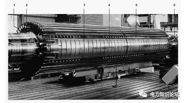
Figure 1-10 Shaft
1-rotor slot; 2-rotor tooth; 3-magnetic pole transverse slot; 4-magnetic pole; 5-damping winding slot; 6-excitation side journal
The uneven distribution of axial slots on the circumference of the rotor body makes the moment of inertia of the direct axis and the transverse axis different, which will cause the rotor to vibrate at double the system frequency. In order to eliminate this vibration, the large teeth of the rotor are provided with transverse grooves to balance the stiffness difference between the straight axis and the horizontal axis. Axial slots for embedding damping slot wedges are opened on the large teeth of the rotor. In the rotor coil slots, the rotor slot wedges act as damper windings.
2) Rotor winding
The rotor winding consists of a series of coils embedded in slots, two coil groups forming a pole. Each coil is composed of several turns connected in series, and each turn is composed of two longitudinal turns and transverse turns, and the turns are brazed together at the end sections. The rotor winding consists of silver-coated deoxidized copper hollow wires with cooling ducts. The turns of the coil are insulated from each other by interlayers. L-shaped epoxy fiberglass fabric with Nomex filler was used as slot insulation. Slot wedges are made of high conductivity material and extend below the shrunk seat of the grommet. The retainer seat is silver plated to ensure good electrical contact between the wedge and rotor retainer.
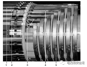
Figure 1-11 Rotor end winding
1-rotor body; 2-slot wedge; 3-inlet of straight line; 4-pad; 5-outlet of end winding
3) Rotor retaining ring
Integral rotor shrouds are used to dampen the centrifugal force of the rotor end windings. The rotor guard ring is made of non-magnetic high-strength steel to reduce stray losses. Each retaining ring is suspended and thermally sleeved on the rotor body. A split ring is used to secure the retaining ring axially.
The retaining ring withstands the centrifugal forces generated by the rotor end windings. One end of the retaining ring is shrunk on the rotor body, and the other end is suspended on the end winding of the rotor without contacting the rotating shaft. The structure of the suspended retaining ring has no interaction with the deflection of the rotating shaft.
The center ring is shrunk on the inner circle of the free end of the retaining ring, supports the retaining ring in the circumferential direction, improves the rigidity of the retaining ring, and supports the coil at the end of the rotor in the axial direction. The ring key prevents axial displacement of the retaining ring.
In order to reduce stray loss and achieve sufficient strength, the retaining ring is made of high-strength anti-magnetic steel by cold processing. The thermal sleeve surface of the retaining ring acts as a short-circuit ring in the damping system. In order to reduce the contact resistance, the thermal sleeve surface is silver-plated.
4) Rotor wedge and damping structure
The rotor wedge is made of copper alloy material with high strength and good electrical conductivity. There is a radial ventilation hole in the middle of the wedge, which protrudes under the overlapping surface of the retaining ring, and ensures a good electrical connection between the wedge and the rotor retaining ring. touch. There are four damping grooves on each magnetic pole of the generator rotor. The material of the damping slot wedge is silver-copper material with excellent conductivity, and the surface of the slot wedge is silver-plated. This results in a better contact with the rotor teeth. The damping wedge bears the eddy current generated by the negative sequence current on the surface of the body. Together with the guard ring to form a circuit, this system has been verified as a very good damping winding system through long-term operation, which can fully meet the negative sequence capability.
The rotor coils are fixed in slots with slot wedges to withstand centrifugal force. The slot wedge extends below the grommet, which doubles as a short-circuit ring for the damper winding. In addition, a damping slot for placing a damping slot wedge is provided on the surface of the magnetic pole.
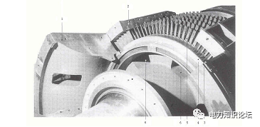
Figure 1-12 Structural diagram of generator rotor fan
1-baffle ring bracket; 2-baffle ring; 3-guide vane; 4-fan hub; 5-fan blade; 6-rotor gas inlet
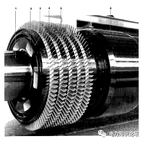
Figure 1-13 Rotor fan
1-rotating shaft; 2-air inlet; 3-balance weight slot; 4-fan seat; 5-fan blade; 6-retaining ring
5) Rotor fan
As shown in Figure 1-12 and Figure 1-13, an axial flow fan equipped with a multi-stage fan at the steam end of the generator provides driving force for hydrogen cooling. The fan consists of moving blades installed at the steam end of the rotor and fixed on the stator steam The side end cover is composed of a static blade duct air device, the fan is installed on the hub which is shrunk on the rotor wheel, and the rotor winding cooling ventilation duct is arranged under the hub. The fan works together with the pressure generated by the exhaust gas from the air outlet along the rotor body to enhance the cooling effect of the rotor winding. The fan blades are installed on the T-shaped slot of the fan base, and the fan base is heat-sleeved on the rotating shaft.


 XINDA
XINDA