Basic knowledge of DC motor structure
main content:
1. Basic knowledge of DC motor
The DC motor can convert mechanical energy into DC electrical energy as a generator, and can also convert DC electrical energy into mechanical energy as a motor.
DC motors are generally used as DC power sources. Due to the development of thyristor technology, it has been gradually replaced. However, its waveform is good and has a large overload capacity. The exciter of the synchronous generator below 100,000kV in the power plant, the charger of the battery, etc. still need to use the DC generator.
The DC motor has smooth speed regulation characteristics, a large speed regulation range and a large starting torque, so it is still used in some industrial sectors. DC motors are also used for powder feeding motors and some control motors in power plants.
One of the main weaknesses of the DC motor is the commutation problem. Due to the existence of this problem, its manufacturing cost is high and its operation and maintenance are troublesome. At present, there is a tendency to replace DC motors with speed-adjustable AC motors and replace DC generators with silicon-controlled rectifiers.
DC generators and DC motors are basically the same in terms of structure and certain electromagnetic conditions.
2. Structure introduction
The structure of a DC motor is the same as that of an AC motor. It has two parts: a stator and a rotor. Its magnetic poles are the stator and the armature is the rotor. Figure 1 shows the basic structure of a DC motor .
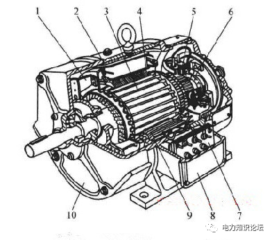
Figure 1 Basic structure of a DC motor
1-fan; 2-frame; 3-armature; 4-main pole; 5-brush holder; 6-commutator; 7-junction box; 8-outlet box; 9-commutation pole; 10-end cover
1. Stator
The stator part of the DC motor is mainly composed of the main magnetic pole, the commutation magnetic pole, the brush device, the machine base and the end cover.
(1) Main magnetic pole: The main magnetic pole is used to generate the main magnetic field for the DC motor to induce electromotive force in the armature winding. It consists of two parts, the iron core and the excitation winding on the iron core, as shown in Figure 2. The core part of the winding lock sleeve is called the pole body, and the pole core is made of low carbon steel plates with a thickness of 1~1.5mm. Its enlarged part near the air gap is called the pole shoe. The main magnetic pole laminated with steel plates can reduce the eddy loss on the surface of the pole piece when the armature rotates. The role of the pole piece is to support the field winding (field coil) and improve the division of the air gap flux density. The excitation winding used to produce the magnetic field is surrounded by insulated round copper wire or flat copper wire, which is sleeved on the main magnetic pole. The pole core and the excitation winding are separated by an insulating frame. Uniform main poleThe ground subdivision is on the inner circle of the base, and its polarity is alternated according to N, S, N, S ....
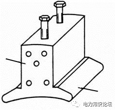
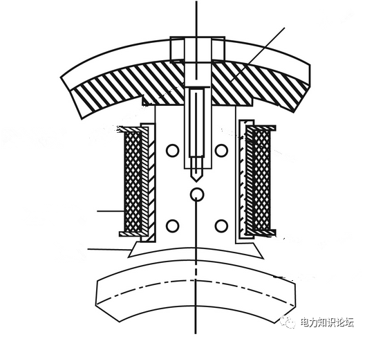
Figure 2 Main poles of a DC motor
(a) The main magnetic pole core made of thin steel sheet ( b) The main magnetic pole is fixed on the base together with the winding
1-pole body; 2-pole shoe; 3-frame; 4-excitation winding
(2) Commutation pole: The structure of the commutation pole is basically the same as that of the main pole. It consists of two parts, the iron core and the excitation winding on the iron core, as shown in Figure 3 . But smaller than the main magnetic pole in volume. Its main function is to solve the commutation problem generated when the DC motor is working, so it is called the commutation pole. The pole core of the reversing pole is usually laminated with a whole piece of steel plate. The commutation pole excitation winding is generally made of flat copper wire with a large area, and the inter-turn pad is insulated. It is connected in series with the armature winding to better improve the commutation problem.
The number of commutation poles is generally the same as the number of main magnetic poles. They are mounted right in the middle of adjacent main poles .
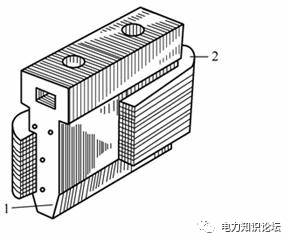
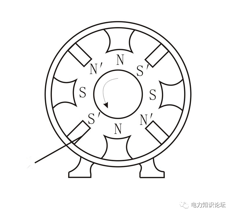
Figure 3 Commutation poles of a DC motor
( a) Structure of commutation poles; (b) Arrangement sequence of commutation poles
1-pole core ; 2-commutation winding ; 3-base
(3) Frame: It is the shell of the motor, used to fix the magnetic poles. Its main part is also called the yoke as the magnetic passage between the poles. It is cast iron or welded with steel plates.
(4) Brush device: The function of the brush is to connect the armature circuit of the rotating part with the external circuit. In addition, the movable contacts of the brushes and the commutator act as mechanical rectifiers. The brush device is composed of brushes, brush holders, brush rods and other parts. Shown below are the brushes and brush holders. The brushes are usually composed of graphite. It is placed in the brush holder and is pressed against the commutator face by a spring. The spring pressure is adjustable. Generally, the number of brushes (that is, the number of brush rods) is equal to the number of main magnetic poles, and the axis of the brushes is aligned with the center line of the main magnetic poles.
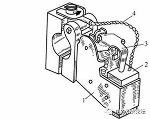
Figure 4 Brush and brush holder
1-brush holder; 2-electric brush; 3-compression spring; 4-soft wire
2. Rotor _
The rotor part of a DC motor is mainly composed of armature core, armature winding, commutator and so on. The center of rotor-type electromechanical energy conversion, so it is also called armature.
(1) Armature core: The armature core is generally laminated with 0.35~0.5mm mutually insulated silicon steel sheets, mainly to reduce the loss of the core, which is different from the composition of the main magnetic pole of the stator, as shown in the figure below . Slots are punched on the silicon steel sheet to place the armature winding, and there are axial ventilation holes on the silicon steel sheet of the DC motor with larger capacity to form an axial ventilation passage. The main function of the armature core is to form a magnetic circuit. ( 2) Armature winding: It is the core part of the motor, which can be used to induce electromotive force, form a circuit, pass current, and realize energy conversion together with the magnetic pole magnetic field. It is made of insulated copper wires one by one, and then placed in the groove and welded according to certain rules. Both ends of each element are welded to different commutator segments, the slots of the windings are pressed tightly with insulating slot wedges, and the ends are bound with latitude-free glass ribbons.
(3) Commutator (commutator): It is a combination of commutation sheets, which are used to form a mechanical rectification device together with brushes, and change the AC potential of the internal winding into a DC potential between the brushes. The commutation sheet has a trapezoidal cross-section Copper (or other copper alloy) row. It has raised tabs protruding from one end for soldering to the component ends of the windings. All commutation photos are embedded in V-shaped steel rings using the lower dovetail. Insulate between the commutation sheet and the copper ring. There are mica sheets (0.6~1.2mm thick) between the sheets of the photo-changing sheet for insulation. Fig. 5 shows a structural diagram of a commutator. Since the commutator is subjected to a large centrifugal force and temperature stress caused by itself during operation, its fastening and selection of appropriate materials are very important.
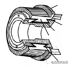
Figure 5 Commutator structure
1-Mica between slices; 2-V-shaped ring; 3-Sleeve; 4-Commuting piece; 5 Mica insulation


 XINDA
XINDA