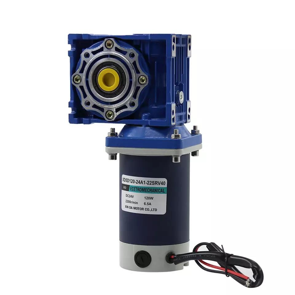
Do you know the specific structure of the gear reduction motor?
1. gear
It is one of the core components in the internal structure of the geared motor . Gears generally use 20CRMNTI as the raw material. After carburizing and quenching, gear grinding steps, the gears have high hardness and strong strength, and are suitable for use under the conditions of high torque and high power. Gears are generally divided into cylindrical gears, bevel gears, non-circular gears, minnows, and worm gears according to their shapes. The tooth shape of the gear includes tooth profile curve, excitation angle, height and displacement. Involute gears are relatively easy to manufacture, so among the gears used in modern times, involute gears account for the vast majority , while cycloid gears and arc gears are less used. In terms of pressure angle, gears with small pressure angles have a smaller load-bearing capacity; gears with large pressure angles have higher load-bearing capacity, but the load on the bearing increases under the same transmission torque, so it is only used in special cases. The tooth height of the gear has been standardized, and the standard tooth height is generally adopted. There are many advantages of shifting gears, which have been widely used in all kinds of mechanical equipment.
2. Out shaft
The shaft is a part of the internal structure of the reducer that goes through the middle of the bearing or the middle of the wheel or the middle of the gear, but there are also a few square ones. A shaft is a mechanical part that supports a rotating part and rotates with it to transmit motion, torque or bending moment. It is generally in the shape of a metal round rod, and each segment can have different diameters. The parts that make rotary motion in the machine are mounted on the shaft. The structural design of the shaft is an important step to determine the reasonable shape and all the structural dimensions of the shaft. It consists of the type, size and position of the parts installed on the shaft, the fixing method of the parts, the nature, direction, size and distribution of the load, the type and size of the bearing, the blank of the shaft, the manufacturing and assembly process, installation and transportation, and the shaft. deformation and other factors. The designer can design according to the specific requirements of the shaft, and compare several schemes if necessary, so as to select the best design scheme.

3. Bearing
The bearing is a component that fixes and reduces the friction coefficient of the load in the internal structure of the reducer. It can also be said that when other parts move relative to each other on the shaft , it is used to reduce the friction coefficient during power transmission and keep the middle position of the shaft fixed. Bearings are an important part of modern mechanical equipment. Its main function is to support the mechanical rotating body to reduce the friction coefficient of the mechanical load during the transmission process of the equipment. According to the different friction properties of moving elements, bearings can be divided into two types: rolling bearings and sliding bearings.
4. Oil seal
The oil seal is a mechanical component used to seal oil, which isolates the parts that need to be lubricated from the output parts in the transmission parts, and prevents the lubricating oil from leaking. Static and dynamic seals. General reciprocating motion seals are called seals. The representative form of oil seal is TC oil seal, which is a double- lip oil seal covered with rubber and self-tightening spring. Generally speaking, oil seal often refers to this kind of TC skeleton oil seal.
5. Cabinet
The box body is an important part of the internal structure of the reducer . It is the base of the transmission parts and should have sufficient strength and rigidity. The cabinet is usually made of gray cast iron, which has good casting performance and vibration damping performance. The cast steel box can also be used for heavy-duty or shock-loaded reducers. For the reducer produced in one piece, in order to simplify the process and reduce the cost, the box body welded by the headstock box body plate of the steel middle section gantry milling machine can be used. In order to facilitate the installation and disassembly of shafting components, the box is made horizontally split along the axis. The upper box cover and the lower box body are connected into one body with bolts .


 XINDA
XINDA