


Introduction to key technologies of new energy vehicles
1. What are the main differences between new energy vehicles and traditional vehicles?
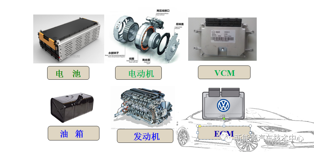
Traditional energy vehicles are based on mechanical systems such as;
Engine - Power machinery.
The mechanical maintenance of traditional energy vehicles is based on image thinking.
New energy vehicles are based on electrical systems such as;
Electric motor, power battery - electrical assembly.
The electrical maintenance of new energy vehicles is based on logical thinking.
2. The core of new energy vehicles is the "three power" technology:
3. Basic composition of pure electric vehicles
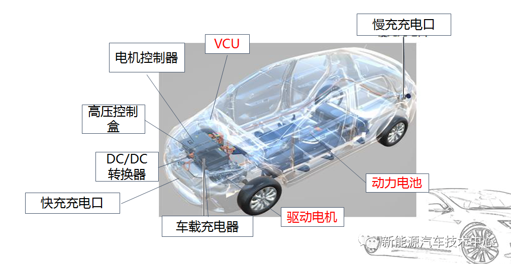
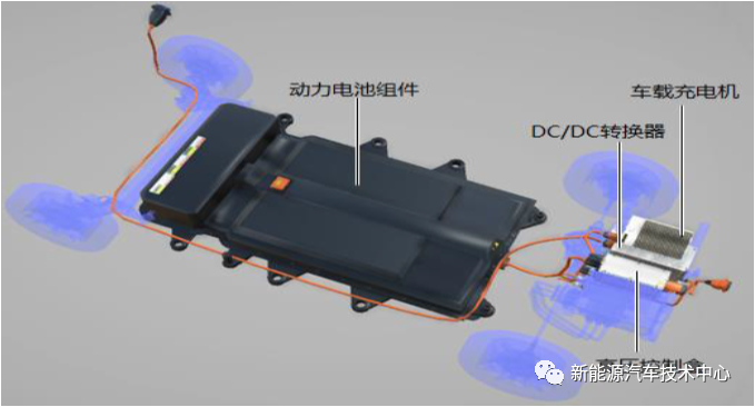
1. Charging system (power battery system)
It consists of power battery components, DC/DC converter, car charger, high voltage control box, fast charging port (DC), slow charging port (AC), etc.
1. Charging system control design
Charging System Control Design Architecture
2. Car charger
The main function of the on-board charger is to convert 220Vac into 320Vdc high-voltage direct current to charge the power battery. At the same time, it provides various protection measures such as overvoltage, undervoltage, overcurrent, and undercurrent. When the charging system is abnormal, the power supply will be cut off.
3. High voltage control box
The high-voltage control box is mainly used for outputting and distributing the electric energy stored in the power battery to realize the cut-off and protection of the branch electrical devices.
The high-voltage control box has a total of 5 wiring ports, which are respectively connected to fast charge, power battery, motor controller and other high-voltage connectors.
High Voltage Control Box - High Voltage Accessory Insert
A: Positive pole of DC/DC power supply B: Positive pole of PTC power supply
C: Positive pole of compressor power supply D: Negative pole of PTC-A group
E: Positive pole of charger power supply F: Negative pole of charger power supply
G: DC/DC power negative pole H: Compressor power negative pole
J: PTC-B group negative pole L: Interlock signal line
K: empty foot
4. DC/DC
The main function of the DC/DC converter is to complete the conversion of 320Vdc to 14Vdc, and supply power to the low-voltage battery and the low-voltage electrical equipment of the whole vehicle; there are 4 terminals, which are the low-voltage output negative pole, the low-voltage output positive pole, the low-voltage control terminal, and the high-voltage input terminal.
5. Power battery system
The power battery system is mainly composed of four parts: power battery module, battery management system, power battery box and auxiliary components.
Power battery module
Battery cell: the smallest unit that constitutes a power battery module.
Battery Module: A group of parallel battery cells that can be replaced as a unit.
Battery module: a combination of multiple battery modules or single cells in series.
Rated voltage = rated voltage of single cell × number of single cells in series;
Battery capacity = single cell capacity × single cell number in parallel;
The total energy of the battery = the rated voltage of the power battery system × the capacity of the power battery system.
Schematic diagram of the basic composition of the power battery high-voltage system
6. Slow charging port (communication)
Slow charging (AC) charging interface parameter values:
Rated voltage 250V,
Rated current 16A, 32A.
7. Fast charging port (DC)
Fast charging (DC) charging interface parameter values:
Rated voltage 750V,
Rated current 125A, 250A.
2. Electric drive system
It is composed of drive motor assembly, motor controller, electric drive cooling system and reducer assembly. It is connected to the vehicle system through high and low voltage wiring harnesses and cooling pipelines.
Connection diagram of electric drive system
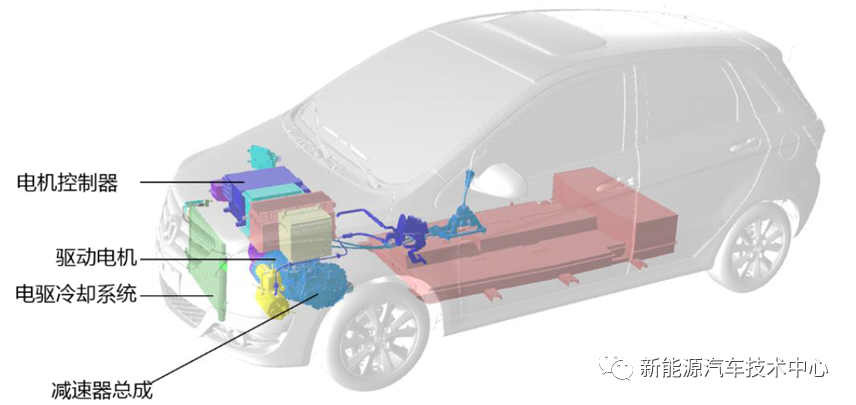
Schematic diagram of electric drive system
The main function of BAIC EV160 electric drive system is to convert electrical energy into mechanical energy, or convert mechanical energy into electrical energy
1. Permanent Magnet Synchronous Motor (PMSM)
High efficiency, small size, light weight and high reliability.
The motor uses some sensors to provide information about the operation of the motor:
Resolver: used to detect the rotor position of the motor;
Temperature sensor: used to detect the winding temperature of the motor.
2. Resolver
Resolver for short is a signal element whose output voltage changes with the rotor angle. When the excitation winding is excited with an AC voltage of a certain frequency, the voltage amplitude of the output winding has a sine or cosine function relationship with the rotor rotation angle, or maintains a certain proportional relationship, or has a linear relationship with the rotation angle within a certain rotation angle range.
3. Motor controller
The motor controller is the control center of the electric drive system, which is mainly composed of a DC-AC inverter module, an AC-DC rectifier module, a temperature protection module and an electronic controller.
Sensors used in motor control systems include current sensors, voltage sensors, and temperature sensors.
3. Electronic control system
Input signal sensors such as accelerator pedal position sensor, brake pedal position sensor, electronic shifter, etc., vehicle controller (VCU), motor controller (MCU), battery management system (BMS) and other control modules and drive motor, power Batteries and other executive components.
The basic composition of the electronic control system
1. Power-on control of the electronic control system
High voltage is powered on, the ignition key is ON, the current state of the BMS and MCU is normal, and there is no serious fault in the whole vehicle during the previous power-on and power-off process.
a) The initialization of BMS and MCU is completed, and the VCU confirms the status;
b) close the battery relay;
c) close the main relay;
d) MCU high voltage power-on;
e) If the gear is in the N gear, the instrument displays the Ready light.
2. Power-off control of the electronic control system
Power-off sequence: The pure electric vehicle can be powered off normally by turning the ignition key to the OFF gear;
1) Turn the ignition key to the OFF position, the main relay is disconnected, and the MCU is powered off under low voltage;
2) The auxiliary system stops working, including DC/DC, water pump, air conditioner, heater;
3) BMS disconnects the battery relay;
4) Power off the vehicle controller (VCU);
The vehicle controller will store the fault information during the driving process before powering off.
3. Fault diagnosis and treatment of electronic control system
The electronic control system makes a comprehensive judgment based on the failure of the motor, battery, EPS, DC/DC and other components, the CAN network failure of the whole vehicle and the VCU hardware failure, determines the failure level of the whole vehicle, and performs corresponding control processing.
|
grade |
name |
Post-failure handling |
|
Level 1 |
fatal failure |
Emergency disconnect high voltage |
|
secondary |
critical failure |
Secondary motor fault zero torque, secondary battery fault 20A discharge current limit power |
|
Level 3 |
General failure |
Entering limp condition/power reduction |
|
Level 4 |
Minor failure |
Only the instrument display, the fourth-level fault is a maintenance prompt, but the VCU does not limit the entire vehicle. Four-level energy recovery failure, only stop energy recovery, driving is not affected.
|
4. Common fault indicator lights of high-voltage system
4. High voltage safety protection
High voltage safety protection mainly includes the following aspects:
1. Continuous leakage detection of the whole vehicle through BMS and leakage sensor (insulation resistance 20MΩ);
2. When the maintenance personnel unplug the plug-in or open the cover of the high-voltage device when the power is on, the high-voltage interlock can make the high-voltage system of the whole vehicle power off immediately, and quickly release the large capacitance in the motor controller, etc.
3. The inertia switch will immediately disconnect the high-voltage system and release the large capacitance when the vehicle has a major collision.
BAIC EV160 high voltage interlock circuit
New energy vehicle vehicle safety protection
Power supply reverse polarity protection, collision protection, active discharge, passive discharge, high voltage interlock, cover opening detection, etc.
 XINDA
XINDA