


The basis and focus of motor selection
Because the characteristics of AC small standard motors , brushless motors , stepping motors , and AC servo motors are different, the key points (confirmation items) to be paid attention to when selecting them are also different.
1. AC small standard motor
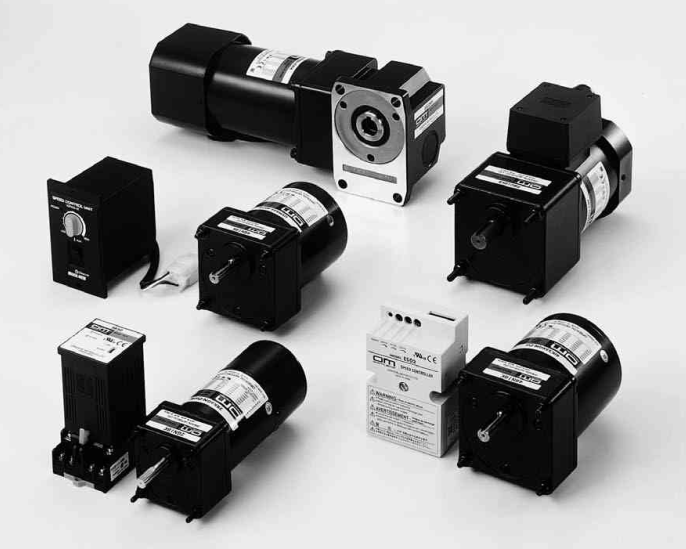
1.1 Rotational speed variation due to load
The actual speed of the AC small standard motor is affected by the load torque, which is several percent lower than the synchronous speed.When choosing an AC small standard motor, it must be selected under the premise that this speed reduction occurs.
1.2 Time rating
Even motors with the same output power have different continuous ratings and short-term ratings due to different types of motors. It should be selected according to the drive time (mode).
1.3 Allowable load moment of inertia of the reducer
When using a combination of a reducer and a motor to perform instantaneous stop (brake, etc.) or frequent intermittent operation, instantaneous forward and reverse operation, etc., due to the excessive load moment of inertia, the reducer may be damaged. less than the allowable load moment of inertia of the machine.
2. brushless motors
2.1 Allowable torque
For a brushless motor combination type product with a dedicated reducer installed, please refer to the table of the allowable torque of the output shaft of the reducer. Please select a product whose load torque does not exceed the allowable torque.
2.2 Allowable load moment of inertia
In order to avoid the alarm caused by regenerative power during deceleration and to realize stable speed control, the brushless DC motor has specified the value of the allowable load moment of inertia. Please select a product whose load moment of inertia does not exceed the allowable value. The combined type has its own allowable load moment of inertia, please select a product that does not exceed this value.
2.3 Payload torque
When the BX series runs and stops frequently, do not make the effective load torque exceed the rated torque. When it exceeds, the overload protection function starts and the motor stops.
3. stepper motors
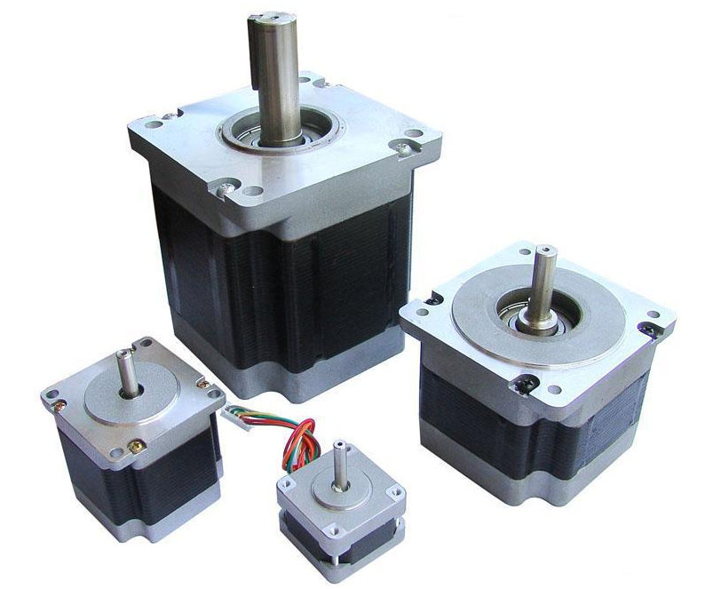
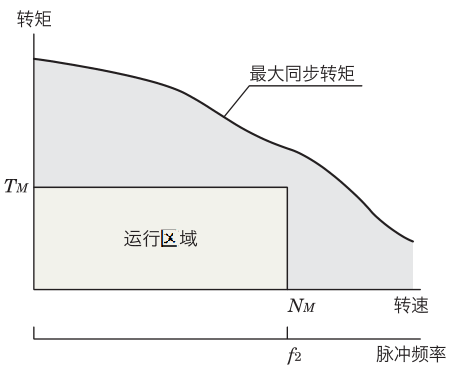
3.1 Confirmation of necessary torque
When selecting a stepping motor, within the maximum synchronous torque, select a motor within the operating range indicated by the operating speed N M (f 2 ) and the necessary torque TM .Reference value of safety factor S f
|
object combination product |
Safety factor (reference value) |
|
2-phase 5-phase stepper motor |
2 |
|
|
1.2 ─ 2 |
3.2 Consideration of temperature rise
If the stepper motor runs continuously for a long time, the temperature will rise, exceeding the heat resistance class 130 (B) temperature inside the motor, and the insulation performance will deteriorate. The temperature rise varies depending on conditions such as operating speed, load conditions, and installation status. Please make the selection based on the operating duty ratio of 50% or less. When the operating duty ratio exceeds 50%, please select a motor with sufficient torque and use the method of reducing the operating current.The public account "Mechanical Engineering Literature", the gas station for engineers!
Running duty cycle = (running time / (running time + stop time)) × 100
3.3 Confirmation of acceleration and deceleration constants
When selecting a stepper motor, the operating area represented by the operating speed N M and the necessary torque T M must be controlled within the maximum synchronous torque. However, for the pulse signal output by the controller, the pulse speed during acceleration and deceleration changes in a step-like manner, and the difference between severe acceleration and deceleration periods will increase. Therefore, under conditions of large load inertia, operation may not be possible even if severe acceleration/deceleration is instructed. In order to make the selected motor run more correctly, please confirm that its acceleration/deceleration constant is above the reference value in the table below.Acceleration/deceleration constant (combined with the reference value of EMP series)
|
object combination product |
Installation size |
Acceleration/deceleration constant T RS [ms/kHz] |
|
5 phase stepper motor |
20, 28, 42, 60 |
20 or more |
|
85 (90) |
over 30 |
|
|
2 Phase Stepper Motor |
20, 28 (30), 35, 42, 50, 56.4, 60 |
above 50 |
|
85 (90) |
Above 75 |
|
|
|
28(30), 42, 60, 85(90) |
0.5 or more* |
Indicates that this item does not need to be confirmed. The values in the table are the lower limit values set by the EMP series.The above acceleration and deceleration constants are also used for deceleration models. However, the following conversions are required when using half-step and micro-step.T RS – Addition and subtraction step constant [ms/kHz]; – Step angle [ °]; – Refer to the table below; i – Reduction ratio of the reduction model coefficient
|
object combination product |
|
|
5 phase stepper motor |
0.72 |
|
2 Phase Stepper Motor |
1.8 |
|
|
0.36 |
3.4 Confirmation of inertia ratio
The inertia ratio is calculated by the following formula.
Inertia ratio = J L / J 0
In the formula: J 0 – moment of inertia of rotor [kg·m 2 ] ; J L – moment of inertia under full load [kg·m 2 ] ;
When using a geared motor
Inertia ratio = J L / (J 0 ·i 2 )
In the formula: J 0 - rotor inertia moment [kg·m 2 ] ; J L - full load moment of inertia [kg · m 2 ] ; i - reduction ratio
If the inertia ratio of the stepping motor is large, the overshoot phenomenon and the backshoot phenomenon during starting and stopping will also increase, which will affect the starting and stabilization time. However, for the pulse signal output by the controller, the pulse speed during acceleration and deceleration changes in steps, and the period difference between severe acceleration and deceleration increases. Therefore, if the inertia is relatively large, it may lead to inoperability. In order to make the selected motor run more correctly, please confirm that its inertia ratio is below the reference value in the table below.The public account "Mechanical Engineering Literature", the gas station for engineers!Inertia ratio (reference value)
|
object combination product |
Installation size |
inertia ratio |
|
2-phase 5-phase stepper motor |
20, 28, 35 |
5 or less |
|
42, 50, 56.4, 60, 85 |
10 or less |
|
|
|
28, 42, 60, 85 |
Below 30 |
If it exceeds the value range in the table, it is recommended to use a deceleration model.4 AC servo motors
4.1 Allowable load moment of inertia
For stable control, the AC servo motor specifies the allowable load moment of inertia. When selecting an AC servo motor, be careful not to allow the load moment of inertia to exceed this allowable value.
|
object combination product |
allowable load inertia |
|
NX series |
Less than 50 times the moment of inertia of the rotor* |
*When automatic gain adjustment is performed, the operation can be performed up to 50 times of the rotor moment of inertia; when the manual gain is adjusted, the operation can be performed up to 100 times.4.2 Rated torque
Driving is possible as long as the ratio of the load torque TL to the rated torque of the AC servo motor is 1.5-2 or more.
Rated torque/load torque≧ 1.5-2
4.3 Instantaneous maximum torque
Make sure that the necessary torque is smaller than the instantaneous maximum torque of the AC servo motor. (At this time, the reference value of the safety factor S f of the required torque is 1.5 to 2)
Also, please note that the time to be able to use the instantaneous maximum torque varies depending on the motor.
Instantaneous maximum torque and usage time
|
object combination product |
usage time |
Instantaneous maximum torque |
|
NX series |
Within about 0.5 seconds |
3 times the rated torque (at rated speed) |
4.4 Payload torque
As long as the ratio of the effective load torque to the rated torque of the AC servo motor, that is, the effective load safety factor is 1.5 to 2 or more, it can be driven.
Effective load safety factor = rated torque / effective cut-off torque
4.5 Settling time
There is a delay in the actual operation of the AC servo motor relative to the position command using the pulse signal. This delay difference is called the settling time.
Therefore, the positioning time calculated according to the operation mode plus the settling time is the actual positioning time.
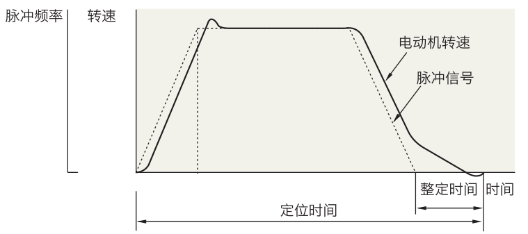
The factory settling time of the NX series is 60 to 70 ms, but the settling time changes when the gain parameter is changed using the mechanical rigidity setting switch.
 XINDA
XINDA