How do all the feedback devices of the motor realize the control of the motor motion?
A servo system performs no better than the feedback device that controls it, imperfect mechanisms for transferring motor power to the load can introduce velocity or position errors into the system, and environmental factors such as electrical noise or temperature can also cause positioning errors. Sometimes errors are acceptable, more often they are not, after all, servo motors can be expensive and people expect them to be the most reliable and accurate of all positioning devices.
When it comes to high-performance servo applications, feedback devices fall into several different categories. Each has its own unique advantages and disadvantages, both electrical and mechanical, that make one more suitable for a particular application than the other.

feedback device location
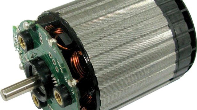
The optimal location for the feedback device is at the load requiring controlled motion, this arrangement eliminates errors from imperfect transmission of motor motion to the load. This sometimes means adding feedback devices to the system in addition to the devices normally installed inside the motor. Brushless motors require position feedback to be incorporated into the motor to provide instant rotor position data for electronic commutation. When a feedback device is mounted on a motor, the periodic and cumulative errors associated with the gearbox and feedback device must be determined to determine if the error is acceptable.
The advantage of a direct drive servo motor is that its internal feedback device is effectively connected directly to the load, eliminating compliance and backlash. In addition to this, components and maintenance are reduced, making direct drive motors an ideal solution for applications requiring precise motion and high bandwidth.

The commutator controls the current to generate torque, which in a permanent magnet motor occurs when the magnetic field from the windings interacts with the magnetic field from the magnets. Optimum torque is produced when current is directed to the appropriate windings. As the motor moves, the position of the windings relative to the magnets changes.
This means that the optimal path for the channel current changes, depending on the motor position. In brushed motors, this is done automatically by brushes and a commutator connected to the armature windings. In a brushless motor, the rotor position is fed back to the driver, which then switches the current through a transistor to the appropriate winding.
absolute or incremental
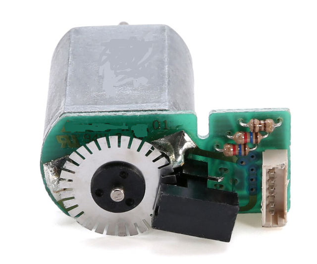
Feedback sensors report absolute or relative incremental position, the former being able to report its position within one electrical cycle when the system is powered up. In contrast, incremental position sensors typically provide output pulses for each increment of motion, but do not reference a specific position within the device's range of motion. This data is combined with periodic marker pulses, machine home switches and counters to know the load position. If the electronic feedback circuit is de-energized, the system will not be able to track its position. For some critical applications using incremental encoders, the controller can be connected to an uninterruptible power supply to maintain position information. Alternatively, a multi-turn absolute encoder would provide the same functionality without maintaining power applied.
The second consideration is the type of technology used in the device, some of the sensors are very robust and target the industrial, machine control industry. Others are relatively fragile and are used more for precision laboratory equipment. Of course, there are also applications with overlapping requirements, such as in semiconductor manufacturing, where conditions demand high precision in a particularly clean environment with high throughput to meet the demanding schedule of high production volumes.

The third consideration is geometry, and the motion system can be linear, rotational, or a combination of the two. Feedback sensors are designed specifically for each situation, and they may have different mounting characteristics and directions of motion, but the basic principles of feedback device operation generally apply to either configuration. For linear systems, in some applications it is necessary to not only find the XYZ axis positioning and position data, but also to indicate the precise position of all axes simultaneously, which is critical for feedback systems. In the event of an emergency stop (emergency stop), being able to restart moving parts when they stop, prevents machine jams and reduces waste. Velocity information is typically obtained from position data by derivatives with respect to time, which makes these devices a "one-stop" purchase for most servo-based systems. For applications that require accurate speed information at low speeds, a feedback device designed for that specific purpose, such as a precision analog tachometer, is sometimes preferred.


 XINDA
XINDA