


How to detect if the wiring sequence of the AC controller plug is different
Some car repair friends have reported that the wiring sequence of the main control plugs of some controllers has changed. We would like to remind everyone to pay attention to this and also popularize the coping methods.
The thing is, the power cord of the main control plug of some controllers has changed, that is, line 1. Here I will give you a detailed analysis. In order not to affect your work efficiency, please read it carefully.
Let's look at the following figure: We use the wiring diagram of the Inbo 35 series controller as the standard. The No. 1 line of the 9-hole plug is the power line ( the positive pole of the vehicle voltage ). This line is connected to the main positive pole of the controller. According to the production practice of the Inbo controller, its color is red or orange. Please remember this No. 1 line, which is also the test power supply of the detector .
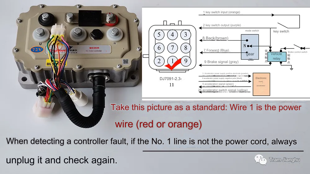
Our AC controllers all have a 9-hole main control plug, which we call a 9-hole male plug. Please note: the controller main control plug is a 9-hole female plug, which is generally a DC permanent magnet controller.
When we test the controller, we should develop a habit. First, we should check whether the No. 1 line of the main control plug is the power line. If it is the power line, it belongs to the scope of routine testing . We can test it by connecting the detector to the 9-hole plug of the controller (the negative pole clip should always be clamped on the negative pole when testing the controller) .
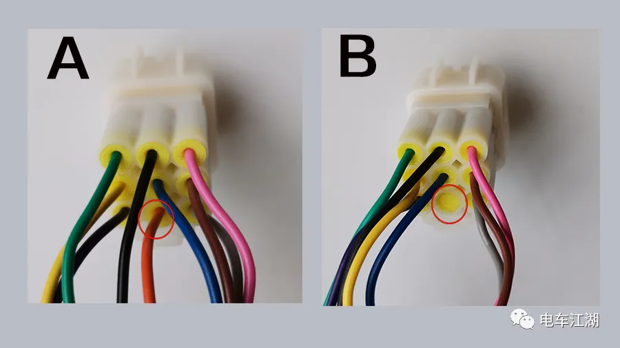
Plug A in the picture below is the conventional type, and this type of controller has a market share of 98%.
Please pay attention to the B plug. Its line 1 is empty and there is no power cord. When we test the controller, we just need to clamp the red clip on the positive pole to conduct the test. That is, the red clip provides a test power supply to the detector.
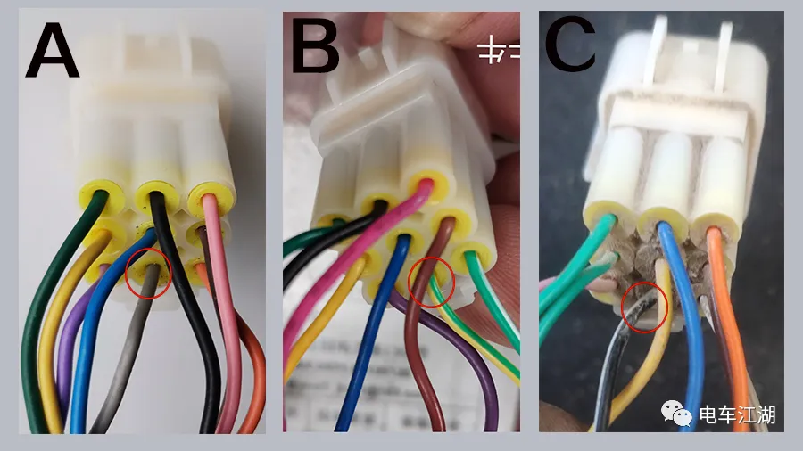
Let's continue to look at the three plug-ins in the picture below. Plug-in A, line 1 is gray (brake line), plug-in B, line 1 is yellow-green (instrument line), and plug-in C, line 1 is black and white (negative electrode of the instrument).
Important things should be said three times: When detecting controller failure, first look at line 1 of the 9-pin plug. If it is a non-power line of type ABC, we must unplug it to test the controller failure.
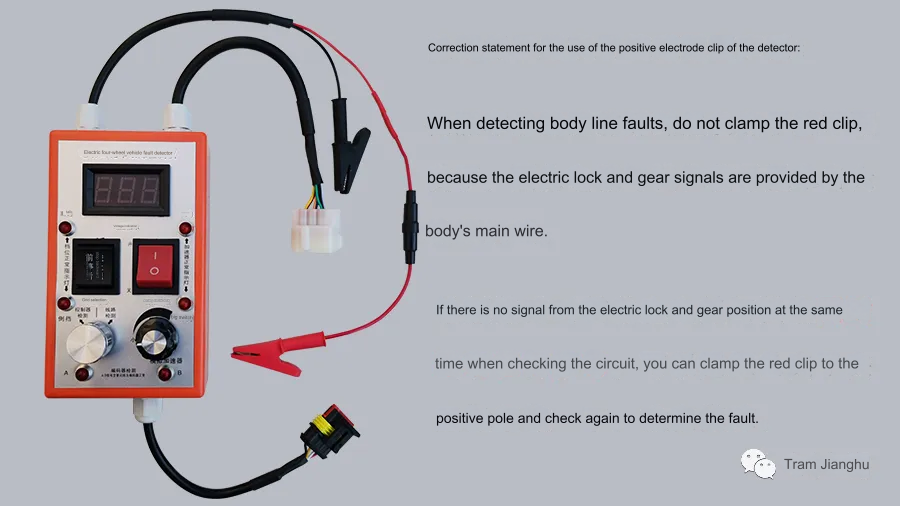
After these non-power lines are unplugged, plug-in line 1 will be empty and the detector will not get the detection power supply. At this time, we need to clip the red clip of the detector to the positive pole of the controller.
Why do we unplug these wires? Because the red clip is connected to the No. 1 power line of the detector. If these functional lines are powered on, abnormalities will occur, affecting fault detection, so they must be unplugged.
The gray line of the A plug No. 1 line in the above picture is the brake line. If it is connected to the power controller, it will enter the brake state, affecting the controller fault detection. Some of the main control plugs of the Inbo 3624/3625 controllers are arranged in this way.
Line 1 of the B plug is the yellow-green instrument function line. If it is connected to the power controller, a fault will be reported, resulting in failure to detect the fault normally. The Xinlianda controller equipped with the Fulu Niu Niu electric four-wheeler has this line sequence arrangement.
The black and white color of line 1 of the C plug is the negative pole of the instrument. If it is connected to the power supply, the fuse of the tester clip will burn. The Xinlianda controller plug equipped with the Li Chi Mi Ka four-wheeler is arranged in this way.
The above problem about Line 1 of the controller main plug is what we actually encountered when testing the controller. Everyone must remember that you must first look at Line 1 of this plug before testing the controller.
While emphasizing that everyone should pay attention to Line 1, we also adjusted the positive clamp of the line detection. It is because of Line 1. In order to avoid conflicts with those special-shaped plug-in function lines, we can directly detect it without clamping it. (This line will be updated in subsequent production.) This line is not very useful, so please note:
The above are our current line adjustments and response methods. If you have any questions, please consult us. If you have any suggestions on the use of the detector, please notify us in time.
It is in our common interest to make the detector a helper for everyone to repair their cars. When many hands make light work, the flames rise high. We hope that everyone can accumulate more maintenance experience and make more suggestions, so that our detector can be turned into a veritable magic tool for car repair.
Thank you all for your support. Lao Gao from the Electric Vehicle Industry is looking forward to communicating and interacting with you for common progress.
 XINDA
XINDA