![]() In today's intelligent era, stepper motors are widely used due to their unique open-loop position control performance. When the stepper motor rotates, each device has certain requirements for the smoothness of its output torque. The stability of rotation is not only related to the main structure of the stepper motor, but also closely related to the control method of the stepper motor.Today I will introduce you to bipolar stepper motors, their structure and control mode.
In today's intelligent era, stepper motors are widely used due to their unique open-loop position control performance. When the stepper motor rotates, each device has certain requirements for the smoothness of its output torque. The stability of rotation is not only related to the main structure of the stepper motor, but also closely related to the control method of the stepper motor.Today I will introduce you to bipolar stepper motors, their structure and control mode.
Basic components of a bipolar stepper motor
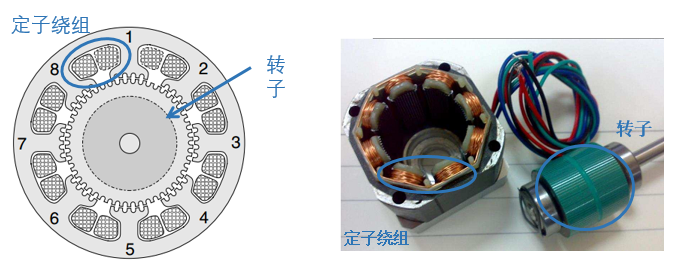
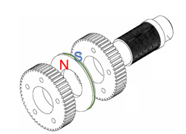
Stepper motors are brushless DC ( BLDC ) motors that rotate in steps of equal length. Bipolar stepper motors are stepper motors that have one winding per phase, specifically two-phase four-wire stepper motors. They consist of two main components: the stator and the rotor (see Figure 1).
Figure 1: Structural diagram of a bipolar stepper motor
stator
The stator is the stationary part of the motor. The eight stators are wound with two-phase bipolar windings, and each stator core has five teeth (see Figure 1).
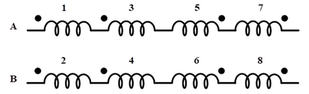
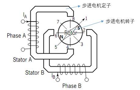
The A-phase winding starts from stator 1 and winds to stators 3, 5, and 7 in sequence (see Figure 2). It is worth noting that the winding directions of stators 1 and 5 are the same, while the winding directions of stators 3 and 7 are the same. The two groups (stators 1 and 5, and stators 3 and 7) are wound in opposite directions. The B-phase winding is also wound on the same principle, with stators 4 and 8 forming a group and stators 2 and 6 forming a group.Figure 2: Winding schematic diagram of bipolar stepper motor
Rotor
Usually, the rotor is attached with axially magnetized permanent magnets. Figure 3 shows the structure of the rotor.
Figure 3: Schematic diagram of rotor structure
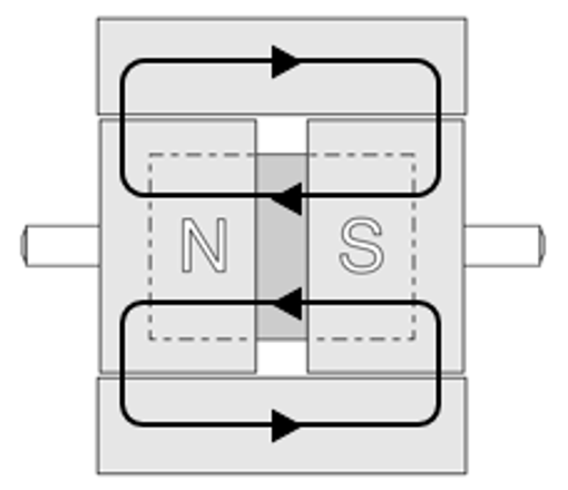
Figure 4 shows a side cross-section of the rotor.
Figure 4: Rotor side cross-section view
The magnetic field lines of the permanent magnets are closed in the motor body. Due to the magnetic field lines and magnetic resistance effect, the stepper motor has a certain locking torque even when it is not powered (see Figure 4).
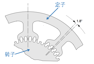
The rotor has 50 teeth, and relative to the stator gear, due to the number of teeth and phase structure, it has a step angle of 1.8 degrees (see Figure 5). Step angle: The mechanical angle that the stepper motor rotor advances when the electrical cycle completes 90 degrees.
Figure 5: Schematic diagram of 1.8° step angle structure
In order to facilitate the explanation of the subsequent control method, we simplify the complex structure diagram into a schematic diagram (see Figure 6).
Figure 6: Simplified schematic of a bipolar stepper motor
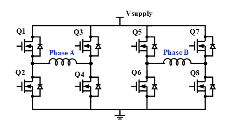
The stator and rotor of the stepper motor can be regarded as having only one tooth each, which makes the stepper motor drive method different from other motors. This method is called dual full-bridge drive, where the A phase winding is connected to the first full-bridge drive and the B phase winding is connected to the second full-bridge drive (see Figure 7).
Figure 7: Dual full-bridge drive circuit diagram
Bipolar stepper motors have three control modes: single-phase stepper, full-step stepper and half-step stepper (see Table 1).
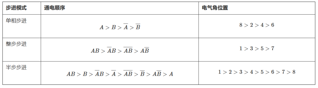
When phase A and phase B are energized in sequence according to the single-phase stepping mode, the stator magnetic field will change accordingly, and the rotor will rotate due to polar attraction. Table 1 details the energization sequence of phase A and phase B ( AB ) and the rotation position of the rotor.
The single-phase stepping process specifically includes three steps, as described below:
1. When A is powered on, the driving current flows from Q1 to Q4. At this time, the upper end of stator A is at N, the lower end is at S, and the rotor rotates to position 8 (see Figure 6).
2. Next, phase B is energized, and the driving current flows from Q5 to Q8. At this time, the left end of stator B is S, the right end is N, and the rotor rotates to position 2 (see Figure 6).
3. The principle of the next two states is similar to the above. After cycling this power-on sequence, the rotor starts to rotate.
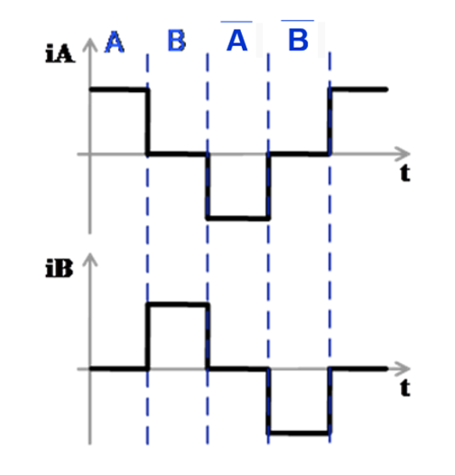
Figure 8 shows the current waveform of the single-phase step AB phase.
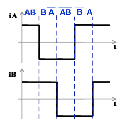
Figure 8: Single-phase stepping AB phase current waveformUnlike single-phase stepping, the AB windings of the full-step stepping are energized at the same time. There are also four corresponding energization modes and rotor electrical positions, but their position space is different from that of single-phase stepping in electrical space. According to the energization sequence of the whole part, the rotor can also rotate. Figure 9 shows the full-step current waveform of the AB phase.Figure 9: Full-step AB phase current waveformThe half-step mode combines the two control methods of single-phase step and full-step step. It has more electrical angle positions, more detailed current waveforms, and smoother rotation.
The non-cyclic half-step mode for single-phase to two-phase operation is shown in Figure 10. This mode generates an 8-step sequence by alternating between full and half steps.
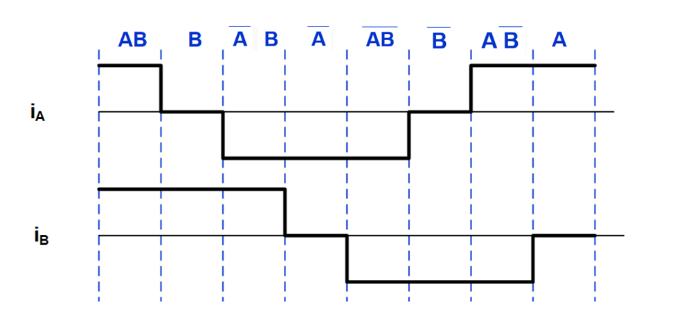
Figure 10: Acyclic half-step mode
Conclusion
This article reviews the basic components of a bipolar stepper motor (stator and rotor), as well as the three main control modes: single-phase stepping, full stepping, and half stepping.


 XINDA
XINDA