


How to control forward and reverse rotation of brushless DC motor
DC motors have fast response, large starting torque, and the ability to provide rated torque from zero speed to rated speed. We know that brushless DC motors in many situations not only require the motor to have good starting and regulating characteristics, but also require the motor to be able to rotate forward and reverse. So how to realize the forward and reverse rotation of brushless DC motor? See below.
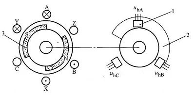
Usually, the forward and reverse rotation of the motor is realized by changing the logical relationship of the inverter switching tube and changing the conduction sequence of each phase of the armature winding. In order to produce the maximum average electromagnetic torque in both forward and reverse rotation of the motor to ensure symmetrical operation, the mutual positional relationship between the rotor position sensor, the main magnetic pole of the rotor and each phase winding of the stator must be designed, as well as the correct logical relationship.
Forward/reverse control (DIR)
The running direction of the motor can be controlled by controlling the on and off of terminal "DIR" and terminal "COM". Terminal "DIR" is internally pulled up to +12 by a resistor, which can be used with passive contact switches or open collector PLC and other control units; when "DIR" and terminal "COM" are not connected, the motor moves clockwise direction (facing the motor shaft), otherwise it will run counterclockwise; in order to avoid damage to the brushless DC driver, when changing the direction of the motor, the motor should be stopped first before changing the direction, and avoid changing the direction of rotation while the motor is running. control.
Speed signal output (SPEED)
The brushless DC driver provides the user with a pulse signal proportional to the motor speed through the terminal SPEED~COM. Number of pulses per revolution = 6 × number of motor pole pairs, SPEED frequency (Hz) = number of pulses per revolution × speed (rev/min) ÷ 60. Example: 4-pole motor, 24 pulses per revolution, when the motor speed is 500 rpm, the output frequency of terminal SPEED is 200Hz.
 XINDA
XINDA