


The unfolded diagram of the motor windings that all motorists must see
The unfolded diagram of the motor windings that all motorists must see, and master the winding embedding process that all motorists should understand
Section 1. Three-phase single-layer chain winding inlay technology
The single-layer chain winding is composed of coils with the same shape, geometric size and pitch connected, and the entire shape is like a long chain. The pitch of each coil of the chain winding is equal and easy to manufacture; the coil end connections are shorter and save copper. Mainly used for 4, 6 and 8 pole small three-phase asynchronous motors with q=2.
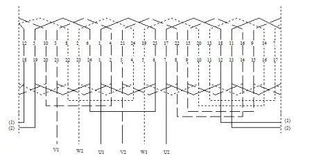
Figure 1 is an expanded view of a three-phase, 4-pole, 24-slot single-layer chain winding. The number of slots per pole and phase is 2, and the coil pitch is 1-6.
figure 1
The upper row of numbers in the expanded diagram indicates the order of embedding wires, and the lower row of numbers indicates the trunking serial number. It can be seen from the figure that each phase has 4 coils.
Each coil has two sides. Usually we call the side that goes down first as the lower side. For example, the side that goes down in the odd-numbered slots in this example (the left side of each coil in the picture) is the lower side; The side that goes down is called the upper side. For example, the side that goes down in the even-numbered slots in this example (the right side of each coil in the picture) is the upper side.
Each upper edge presses two lower edges. For example, in this example, the upper edge under slot 6 presses the lower edge under slots 5 and 3. It can be seen that when inlaying single-layer chain windings, it must be Lift two coils and lower them last, that is, there are 2 coils on the hoist. The steps of embedding wire are to embed the lower layer edge first, then the upper layer edge; and finally embed the upper layer edge of the two hoisted coils.
The specific embedding sequence is as follows:
(1) Select the first slot position, close to the cable outlet of the machine base.
(2) Embedding slot 1 (lower side of the first coil of U phase), and lifting the upper side.
(3) Empty slot 24, insert slot 23 (the lower side of the first coil of W phase), and lift the upper side.
(4) Empty another slot 22 and insert it into slot 21 (the lower edge of the first coil of V phase). The upper edge presses the lower edge of slot 1 and slot 23 at a pitch of 1-6 and is embedded in slot 2.
(5) Empty another slot 20 and insert it into slot 19 (the lower edge of the second U-phase coil). The upper edge presses slot 23 with a pitch of 1-6, and the lower edge of slot 21 is embedded into slot 24. The connection relationship between this coil and the first coil of this phase is that the upper edge is connected to the upper edge or the lower edge is connected to the lower edge, that is, tail, tail or head, head are connected.
(6) After that, the W and V phases are embedded in the empty slot into the next slot, and the four coils of the U, W, and V phases are embedded in turn. Finally, insert two handle coils, and now the entire winding is fully embedded.
The wire embedding rule of single-layer chain winding is: insert 1 slot, leave 1 slot empty, and hang 2 coils. The abbreviation is "embedded 1 empty 1 hanging 2".
According to this method of embedding wires, the bridge wires between the same-phase coils do not need to be cut off. When connecting, pay attention to turning the handles so that they are connected head to head and tail to tail. The last 6 wire ends left out are the terminals with the same name, such as V1, U1, W1 and W2, V2, U2.
Section 2. Three-phase single-layer concentric winding embedding process
Concentric windings are composed of several coils with different geometric sizes and pitches connected into a concentric coil group. The concentric winding end connection is longer and is suitable for 2-pole small three-phase asynchronous motors with even numbers such as q=4, 6, 8, etc.
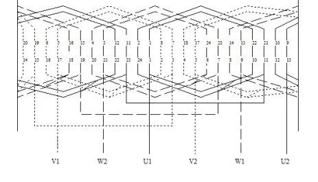
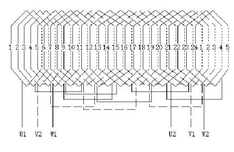
Figure 2 is an expanded view of a three-phase, 2-pole, 24-slot single-layer concentric winding. The number of slots per pole and phase is 4, and the pitch is 1-10, 24-11 (see U phase).
The upper row of numbers in the expanded diagram indicates the order of embedding wires, and the lower row of numbers indicates the trunking serial number. It can be seen from the figure that each phase has two sets of coils, and each set of coils consists of two concentric coils. The lower edge of the coil (the left side of each coil in the picture) is embedded in slots 1, 24, 21, 20, 17, 16, 13, 12, 9, respectively.
8, 5, and 4; the upper edge (the right side of each coil in the picture) is embedded in the remaining slots. The two upper edges of each group press four lower edges. For example, the upper edge slots 10 and 11 of the first group of U-phase coils press the lower edge slots 9 and 8 of the W phase and the lower edge slots 5 and 8 of the V phase. 4. It can be seen that there are 4 hanging coils in this inlay process.
figure 2
The steps of embedding the wires are still to embed the lower layer edge first, then the upper layer edge; and finally embed the upper layer edge of the four hoisted coils. The specific embedding order is as follows:
1) Select the first slot position, close to the cable outlet of the machine base.
2) Embedding slots 1 and 24. Insert the lower edge of the first group of small coils in the U phase into slot 1, and the lower edge of the large coil into slot 24; their upper edges are not embedded (handle coils).
3) Two slots (slots 23 and 22) are empty, slots 21 and 20 are embedded (the two lower edges of the first group of W-phase coils), and the upper edge is not embedded (the handlebar coil).
4) Empty two more slots (slots 19 and 18), insert slots 17 and 16 (the two lower edges of the first group of V-phase coils), and press the four upper edges of slots 1, 24, 21, and 20 according to the pitch. The lower edge is embedded in slots 2 and 3.
5) According to the method of inserting two empty slots into two slots, embed the remaining coils in sequence, and finally embed the hanging handle coils into the slots in sequence.
The rule of embedded lines is: embedded 2 empty, 2 hanging 4.
According to this method of embedding wires, the bridge wires between the same-phase coils do not need to be cut off. When connecting two groups of coils in the same phase, pay attention to turning the handles so that they are connected end to end; each group of concentric coils should be connected in series, connected end to end. The last 6 wire ends left out are the terminals with the same name, such as V1, U1, W1 and W2, V2, U2.
The difference between three-phase single-layer concentric winding and single-layer chain winding
Single-layer concentric winding has two or more coils concentrically nested together to form a pole phase group, while single-layer chain winding has the same size or pitch of each coil. For example: a 3-phase, 2-pole, 24-slot motor generally uses concentric windings with two coils nested together. A 3-phase, 4-pole, 24-slot motor has only one coil per pole and phase, and the sizes or pitches of all coils are the same. Are the same.
Section 3. Three-phase single-layer crossed winding embedding process
The single-layer crossed winding is composed of two coil groups with different coil numbers and pitches. The shape, geometric size and pitch of the coils in the same group are the same, and the ends of each coil group cross each other. Crossed winding consists of two large and small coils arranged crosswise.
The single-layer cross-winding coil has shorter end connections, which is beneficial to saving materials and copper. It is widely used in small three-phase asynchronous motors with q>1 and odd numbers.
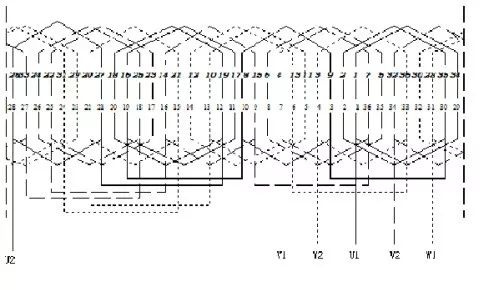
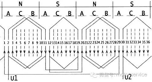
Figure 3 is an expanded view of a three-phase, 4-pole, 36-slot single-layer crossed winding. The number of slots per pole and phase is 3, and the coil pitch is two: one is 1-9, and the other is 1-8.
image 3
The upper row of numbers in the expanded diagram indicates the order of embedding wires, and the lower row of numbers indicates the trunking serial number. It can be seen from the figure that each phase is composed of 6 coils, including two small coils with a pitch of 1-8, and four large coils forming two groups with a pitch of 1-9. The lower edge of the coil (the left side of each coil in the picture) is embedded in slots 1, 2, 4, 7, 8, 10, 13, 14, 16, 19, 20..., and the upper edge (each coil in the picture) on the right side) are embedded in slots 29, 30, 33, 35, 36, 3, 5, 6... in sequence.
Each upper layer edge presses three lower layer edges. For example, the upper layer edge embedded in slots 29 and 30 presses the lower layer edge embedded in slots 31, 32, and 34. It can be seen from this that the hanging coil of this wire embedding method is 3 Bundle. The steps of embedding the wires are still to embed the lower layer edge first, then the upper layer edge; and finally embed the upper layer edge of the three hoisted coils.
The specific embedding order is as follows:
(1) Select the position of the first slot, close to the cable outlet of the machine base.
(2) Insert slots 1 and 2 (the lower side of the two large U-phase coils, lead out the wire end U1), and lift the upper side (handle coil).
(3) Empty slot 3, insert slot 4 (lower side of W-phase small coil, lead wire end W2), lift the upper side (handle coil)
(4) Empty two more slots 5 and 6, and insert slots 7 and 8 (the lower side of the V-phase large coil, leading out the wire head V1). The upper side presses the three lower sides of slots 1, 2, and 4 according to the pitch 1-9. Embedding grooves 35 and 36 respectively.
(5) Empty another slot 9 and insert slot 10 (the lower edge of the U-phase small coil, the connection method of the large and small U-phase coils is that the upper edge is connected to the upper edge, and the lower edge is connected to the lower edge), and the upper edge is connected according to the section The three lower edges of the pressing grooves 4, 7, and 8 are embedded in the groove 3 from 1 to 8.
(6) Empty two more slots 11 and 12 and insert slots 13 and 14 (the lower side of the W-phase large coil, the connection method of the W-phase large and small coils is that the upper side is connected to the upper side, and the lower side is connected to the lower side), The upper edge presses the three lower edges of grooves 7, 8, and 10 according to the pitch 1-9 and is embedded in grooves 5 and 6 respectively.
(7) Empty another slot 15 and insert it into slot 16 (the lower side of the V-phase small coil). Then embed the U, W, and V three-phase coils into the slots in sequence according to the above method, and finally embed the hanger coil into the slots.
The rule of embedded lines is: embedded 2 and empty 1, embedded 1 and empty 2... hanging 3.
According to this method of embedding wires, the bridge wire in the middle of the same-phase coil does not need to be cut off. Each group of large coils in the same phase should be connected in series, end to end; when connecting large and small coils, attention should be paid to turning the handle so that the large and small coils are connected head to head and end to end. The last 6 wire ends left out are the terminals with the same name, such as V1, U1, W1 and W2, V2, U2.
Section 4. Wire embedding process for three-phase double-layer windings
The effective sides of the upper and lower coils are placed in each slot of the double-layer winding. Each effective side of the coil is placed on the upper layer of a certain slot, and the other effective side is placed on the lower layer of another slot separated by y. The pitch of the double-layer winding can be changed, and the appropriate pitch can be selected to improve the waveform of the electromotive force or magnetomotive force, and the technical performance is better than that of the single-layer winding. Generally, slightly larger capacity motors use double-layer windings.
Figure 4 is an expanded view of a three-phase, 4-pole, 24-slot double-layer winding. The number of slots per pole and phase is 2, and the coil pitch is 1-6.
The numbers in the middle of the expanded diagram represent the slot number. There are two lines drawn in each slot. The solid line represents the upper side of the double-layer winding, and the dotted line represents the lower side of the double-layer winding. Each phase has 8 coils, divided into 4 groups and 16 sides, respectively embedded in the lower side of 8 slots and the upper side of 8 slots. For example, U-phase winding slots 1, 2, 6, and 7 form a group with two coils. Slots 1 and 2 are embedded in the upper edge, and slots 6 and 7 are embedded in the lower edge; slots 7, 8,
Figure 4
12, 13, 13, 14, 18, 19, 19, 20, 24, 1 are embedded in the other 3 groups, slots 7, 8, 13, 14, 19, and 20 are embedded in their upper edges respectively, and the remaining slots are embedded in their lower edges. Each upper edge presses 5 lower edges. For example, the upper edge of U-phase 7 slot presses the lower edge of U-phase coils 2-7, the lower edges of V-phase coils 3-8 and 4-9, and the lower edge of W-phase coil 5- 10, the lower side of 6-11.
Therefore, this kind of embedding process must first embed the lower edges of 5 coils, lift the upper edges of 5 coils, then embed the 5 lower edges, 5 upper edges in sequence... and finally embed the 5 lifted edges. Upper edge embedded. The specific embedding steps are as follows:
(1) Select the first slot position, close to the cable outlet of the machine base.
(2) Embed the lower edge of a coil with a pitch (the pitch is 5 in this example), such as U-phase coils 1-6, 2-7, V-phase coils 3-8, 4-9, and W-phase coils 5-10 The lower edges are embedded in slots 6, 7, 8, 9, and 10 respectively. The upper edge is not embedded for the time being and serves as the suspension coil.
(3) Put interlayer insulation on the lower edge of the embedded layer. Then embed the lower edges of the next five coils (embedded in slots 11, 12, 13, 14, 15), and then embed the upper edge of each coil (embedded in slots 6, 7, 8, 9, 10). Continue in sequence until the upper and lower edges of other coils are embedded. Finally, insert the upper edge of the sling coil into the slot.
Wire embedding rule: Each coil is continuously embedded in the slot, and the hanging handle coil is equal to one pitch.
A review of three-phase asynchronous motor winding embedding methods
1. The wire embedding steps of the single-layer winding of a three-phase asynchronous motor can be summarized as follows: first embed the lower layer edge in order, and then embed the upper layer edge. The number of "embedded" ones is determined by the number of handles on the lower layer; the "empty number" by the number of slots between the adjacent lower layer edges. The upper layer edge of a coil presses the lower layer edges of several coils, which is called the "hanging number". It is referred to as "embedded number, empty number, hanging number". The wire embedding steps of the double-layer winding can be summarized as follows: first embed the lower layer edge of one pitch in order, and then embed the upper layer edge of one pitch; the hanger coil is the upper layer edge of one pitch.
2. The number of turns of each component of a larger motor is not very large. Before preparing to embed the wire, count the component in your hand one turn at a time like counting turns, hold it flat in your hand and then embed it in sequence. It is nothing more than straightening out the wires turn by turn (when winding multiple wires together, use multiple wires as a unit) to prevent them from crossing.
6. The first side of the component is pulled in, and the second side of the component is drawn in.
 XINDA
XINDA