B L O G
XINDA MOTOR
  1. Home
  2. Knowhow

Damage to motor caused by inverter

Date:2023-11-21   Author:XINDA MOTOR

Although the phenomenon of motor damage caused by frequency converters has attracted more and more attention, people still do not know the mechanism causing this phenomenon, let alone how to prevent it.


1

Damage to motor caused by inverter


The damage caused by the frequency converter to the motor includes two aspects: damage to the stator winding and damage to the bearings. This kind of damage usually occurs within a few weeks to ten months, and the specific time depends on the brand of the inverter, the brand of the motor, the power of the motor, the carrier frequency of the inverter, the length of the cable between the inverter and the motor, the ambient temperature, etc. Many factors are related. Early accidental damage to the motor brings huge economic losses to the company's production.

This loss is not only the cost of motor repair and replacement, but more importantly, the economic loss caused by unexpected production shutdown. Therefore, when using a frequency converter to drive a motor, sufficient attention must be paid to the problem of motor damage.


2

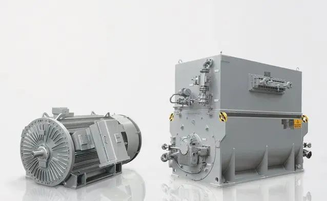
The difference between inverter drive and industrial frequency drive


To understand the mechanism why industrial frequency motors are more susceptible to damage under inverter driving conditions, first understand the difference between the voltage of inverter driven motors and the industrial frequency voltage. Then learn how this difference adversely affects the motor.

The basic structure of the frequency converter includes a rectifier circuit and an inverter circuit. The rectifier circuit is a DC voltage output circuit composed of ordinary diodes and filter capacitors, and the inverter circuit converts the DC voltage into a pulse width modulated voltage waveform (PWM voltage). Therefore, the voltage waveform of the inverter-driven motor is a pulse waveform with changing pulse width, rather than a sine wave voltage waveform. Driving the motor with pulse voltage is the fundamental reason why the motor is easily damaged.

3

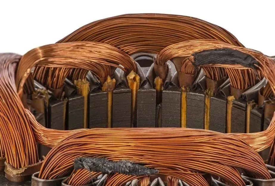
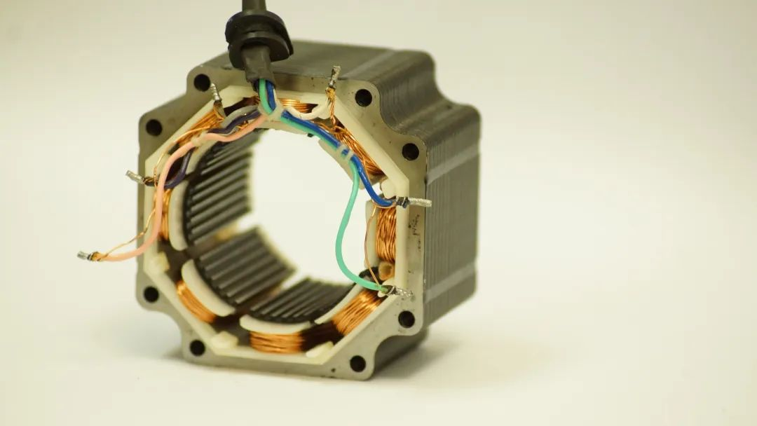
The mechanism of inverter damage to motor stator windings


When the pulse voltage is transmitted on the cable, if the impedance of the cable does not match the impedance of the load, reflection will occur at the load end. The result of reflection is that the incident wave and the reflected wave are superimposed to form a higher voltage. Its amplitude can reach up to 2 times the DC bus voltage, which is approximately 3 times the input voltage of the frequency converter. Excessive peak voltage is applied to the coil of the motor stator, causing voltage impact on the coil. Frequent overvoltage impact will lead to premature failure of the motor.

After a motor driven by an inverter is impacted by a voltage spike, its actual life is related to many factors, including temperature, pollution, vibration, voltage, carrier frequency, and coil insulation technology.


The higher the carrier frequency of the frequency converter, the closer the output current waveform is to a sine wave, which will reduce the operating temperature of the motor and thereby extend the life of the insulation. However, a higher carrier frequency means a greater number of voltage spikes per second, and a greater number of shocks to the motor. Figure 4 shows the variation of insulation life with cable length and carrier frequency. For a 200-foot cable, when the carrier frequency is increased from 3kHz to 12kHz (a 4-fold change), the insulation life decreases from approximately 80,000 hours to 2 Ten thousand hours (a difference of 4 times).

The higher the temperature of the motor, the shorter the life of the insulation. When the temperature rises to 75°C, the life of the motor is only 50%. For motors driven by inverters, since the PWM voltage contains more high-frequency components, the motor temperature will be much higher than when driven by industrial frequency voltage.

4

The mechanism of inverter damage to motor bearings


The reason why the frequency converter damages the motor bearings is that there is current flowing through the bearings, and this current is in a state of intermittent connection. The intermittently connected circuit will generate arcs, and the arcs will burn the bearings.

There are two main reasons for the current flowing in the bearings of AC motors. First, the induced voltage caused by the imbalance of the internal electromagnetic field. Second, the high-frequency current path caused by stray capacitance.

The magnetic field inside an ideal AC induction motor is symmetrical. When the currents in the three-phase windings are equal and the phase difference is 120 degrees, no voltage will be induced on the shaft of the motor. When the PWM voltage output by the frequency converter causes the magnetic field inside the motor to be asymmetric, a voltage will be induced on the shaft. The amplitude of the voltage is 10~30V, which is related to the driving voltage. The higher the driving voltage, the higher the voltage on the shaft. high.


When the value of this voltage exceeds the dielectric strength of the lubricating oil in the bearing, a current path is formed. At some point during the rotation of the shaft, the insulation of the lubricating oil blocks the current flow. This process is similar to the on-off process of a mechanical switch. During this process, an arc will be generated, which will ablate the surface of the shaft, balls, and bowl, forming pits. If there is no external vibration, small dents will not have an excessive impact, but if there is external vibration, grooves will be produced, which will have a great impact on the operation of the motor.

In addition, experiments show that the voltage on the shaft is also related to the fundamental frequency of the inverter output voltage. The lower the fundamental frequency, the higher the voltage on the shaft and the more serious the bearing damage.

In the early stages of motor operation, when the lubricating oil temperature is low, the current amplitude is 5-200mA. Such a small current will not cause any damage to the bearings. However, when the motor runs for a period of time, as the temperature of the lubricating oil increases, the peak current will reach 5-10A, which will cause flashover and form small pits on the surface of the bearing components.

5

Protection of motor stator windings


When the length of the cable exceeds 30 meters, modern frequency converters will inevitably produce peak voltages at the motor end, shortening the life of the motor. There are two ideas to prevent motor damage. One is to use a motor with higher winding insulation resistance (generally called a variable frequency motor), and the other is to take measures to reduce the peak voltage. The former measure is suitable for new projects, and the latter measure is suitable for transforming existing motors.
There are currently four commonly used motor protection methods:

1)  Install a reactor at the output end of the frequency converter: This measure is the most commonly used, but it should be noted that this method has a certain effect on shorter cables (less than 30 meters), but sometimes the effect is not ideal.

2)  Install a dv/dt filter at the output end of the frequency converter: This measure is suitable for situations where the cable length is less than 300 meters. The price is slightly higher than that of the reactor, but the effect is significantly improved.

3)  Install a sine wave filter at the output end of the frequency converter: This measure is ideal. Because here, the PWM pulse voltage is changed into a sine wave voltage, so that the motor works under the same conditions as the power frequency voltage, and the problem of peak voltage is completely solved (no matter how long the cable is, there will be no peak voltage) .

4)  Install a peak voltage absorber at the interface between the cable and the motor: The disadvantage of the previous measures is that when the power of the motor is large, the size, weight and price of the reactor or filter are large. In addition, the reactor Both the inverter and the filter will cause a certain voltage drop and affect the output torque of the motor. These shortcomings can be overcome by using a frequency converter peak voltage absorber.