


Detailed explanation of three-phase induction motor
One-third of the world's electricity consumption is used to operate induction motors that drive pumps, fans, compressors, elevators and various machinery. AC induction motors are a common form of asynchronous motors whose operation depends on three electromagnetic phenomena:
Motor Action: When an iron rod (or other magnetic material) is suspended in a magnetic field so that it can rotate freely, it aligns with the magnetic field. If the magnetic field is moving or rotating, the iron rod will move with the moving field to maintain alignment.
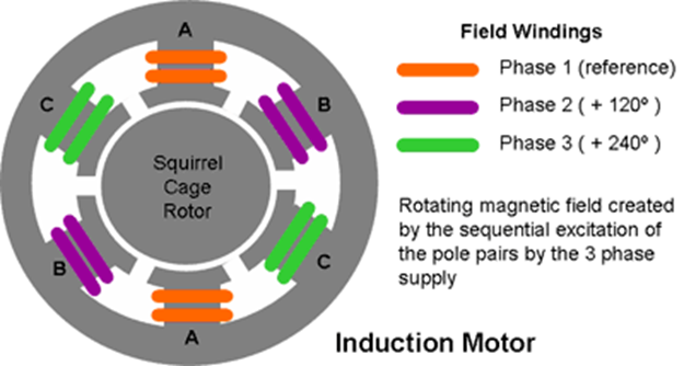
Rotating magnetic field: A rotating magnetic field can be generated from fixed stator poles by driving each pole pair from a different phase of the AC source.
Transformer Action: The current in the rotor winding is induced by the current in the stator winding without direct connection from the source to the rotating winding.
An induction motor can be thought of as an AC transformer with a rotating secondary winding.
The rotating magnetic field is generated by the polyphase excitation of the stator windings. In the three-phase motor example below, when the current applied to the winding of pole pair A (Phase 1) passes its peak value and begins to decrease, the flux associated with the winding also begins to weaken, but at the same time the next pole pair B (Phase 1) The current in the winding of Phase 2) and its associated flux are rising. At the same time, the current through the winding of the previous pole pair C (Phase 3) and its associated flux will be negative and rising (toward a positive value). The net effect is that a flux wave is created as the flux generated by the stator poles rotates around the machine axis from one pole to the next at the frequency of the applied voltage. In other words, the rotating magnetic flux field appears to the stator as the north and south poles of the magnets rotating around the stator.
The size of the rotating magnetic flux wave is proportional to the applied MMF. Ignoring the influence of the back electromotive force generated by the induced current in the rotor winding, the magnetic flux density B will be proportional to the applied voltage.
The stator carries the motor's primary winding and is connected to the power supply. There is usually no external connection to the rotor carrying the secondary winding. Instead, the rotor windings are short-circuited.
When current flows in the stator winding, the action of the transformer induces a current in the short-circuited secondary winding. The magnitude of the rotor current will be proportional to the flux density B in the air gap (and the relative motion of the rotor with respect to the rotating field, called slip, as shown below).
Torque is produced by the reaction between the induced rotor current and the air gap flux generated by the stator current.
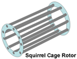
Various rotor types are used. The most popular AC motors use a "squirrel cage" rotor, which consists of copper or aluminum bars fixed between conductive end rings to provide a short-circuit path for current induced in the bars.
Since there are no connections to the rotating windings, expensive commutators can be eliminated, thereby eliminating a potential source of unreliability.
Torque generation (motor action):
When the motor is first started and the rotor is stationary, the action of the transformer induces a current in the rotor windings (conductors). Another way of looking at this is that the relative motion of the rotating flux through the slower moving (initially stationary) rotor windings causes a generator action causing current to flow in the windings.
Once current flows into the rotor windings, Lorentz forces on the conductors produce motor action. The reaction between the current flowing in the rotor conductors and the magnetic flux in the air gap causes the rotor to rotate in the same direction as the rotating magnetic flux, as if it was being dragged by a flux wave.
Similar to a DC motor, the torque T in an induction motor is directly proportional to the flux density B and the induced rotor current I.
T = k1 BI
where k1 is a constant that depends on the number of stator turns, phases and magnetic circuit configuration.
Due to the motor action described above, the rotor speed gradually increases, but at the same time the relative motion between the rotating stator magnetic field and the rotating rotor conductors decreases. This in turn reduces the action of the generator, thereby reducing the current in the rotor conductors and the torque on the rotor. When the speed of the rotor approaches the speed of the rotating magnetic field (called synchronous speed), the torque on the rotor drops to zero. Therefore, the speed of an induction motor can never reach synchronous speed, so an induction motor is an asynchronous motor
slippage
The relative motion between the rotating magnetic field and the rotating rotor is called slip and is given by:
S = Ns- Nr
Ns
where S is slip, Ns is synchronous speed in RPM, and Nr is rotor speed.
Since the rotor current is proportional to the relative motion between the rotating magnetic field and the rotor speed, both the rotor current and torque are proportional to slip.
The rotor current is proportional to the rotor resistance. Increasing rotor resistance reduces current flow and increases slip; therefore, wound rotor motors allow some form of speed and torque control. Increasing the rotor resistance also has the added benefit of reducing input inrush current and increasing starting torque at switch-on, but all of these benefits come at the expense of a more complex rotor design and unreliable slip rings to feed the rotor windings.
Synchronous speed (RPM) is given by:
Ns = 120(f)
p
where f is the power line frequency in Hz and p is the number of poles per phase. p must be an even number because every north pole has a corresponding south pole.
The table below shows the motor speed at different AC mains frequencies for motors with different pole numbers.
|
Rotor speed (rpm) |
||||||
|
Number of poles |
2 |
4 |
6 |
8 |
10 |
12 |
|
50 Hz |
3000 |
1500 |
1000 |
750 |
600 |
500 |
|
60 Hz |
3600 |
1800 |
1200 |
900 |
720 |
600 |
The actual speed of a motor depends on the load it must drive. Increasing the load on a motor causes it to slow down and increase slip. When the motor torque is equal to the load torque, the motor speed will stabilize at the equilibrium speed. This occurs when slip provides just enough current to deliver the required torque.
Early machines were designed with multiple poles to facilitate speed control by changing poles. A limited number of fixed speeds can be obtained by switching different numbers or combinations of poles.
However, the speed of an induction motor can be varied within a limited range by changing the rotor resistance, as discussed in the slip section, but only by using a wound rotor design, thus negating many of the advantages of induction motors.
Since motor speed depends on the speed of the rotating field, speed control can be achieved by varying the frequency of the AC power supplied to the motor.
Like most machines, induction motors are designed to operate at flux densities just below their saturation point throughout most of their operating range for optimal efficiency.
The magnetic flux density B is given by:
B = k2 V
f
where V is the applied voltage, f is the mains frequency, and k2 is a constant that depends on the shape and configuration of the stator poles.
In other words, if the magnetic flux density is constant, then the volts/hertz are also constant. This is an important relationship that has the following consequences.
For speed control, the supply voltage must increase synchronously with the frequency, otherwise the magnetic flux in the machine will deviate from the desired optimal operating point. Therefore, a practical motor controller based on frequency control must have a method to simultaneously control the motor supply voltage. This is called volt/hertz control.
Increasing the frequency without increasing the voltage will cause the magnetic flux in the magnetic circuit to decrease, thereby reducing the output torque of the motor. Reduced motor torque tends to increase slip relative to the new supply frequency. This in turn causes greater current to flow in the stator, thereby increasing the IR voltage drop across the windings and the I2R copper losses in the windings. The result is a significant drop in motor efficiency. Further increases in frequency will eventually cause the motor to stall.
Increasing voltage without increasing frequency can cause the material in the magnetic circuit to saturate. Due to I2R losses in the windings and high eddy current losses in the magnetic circuit, excessive current will flow, resulting in high heat dissipation and ultimately motor failure due to overheating. Increasing voltage will not force the motor past synchronous speed because the torque drops to zero as it approaches synchronous speed.
Frequency conversion is usually provided by an inverter.
Also note that since the induced current in the rotor is proportional to the flux density, which in turn is proportional to the line voltage, the torque depends on the product of the flux density and the rotor current and the square of the line voltage V.
If an induction motor is forced to run faster than synchronous speed, the load torque exceeds the machine torque and the slip becomes negative, causing the rotor induced electromotive force and rotor current to reverse. In this case, the machine will act as a generator, with energy returned to the power source.
If the AC supply voltage to the stator excitation is simply removed, it is not possible to generate electricity because no current will be induced in the rotor.
Therefore, in traction applications, regenerative braking is not possible below synchronous speed in machines powered by a fixed frequency mains supply. However, if the motor is powered by a variable frequency inverter, regenerative braking can be achieved by reducing the supply frequency so that the synchronous speed is less than the motor speed.
AC motors can be finely controlled by a microprocessor and can regenerate current to almost a standstill, whereas a DC motor's regenerative capabilities disappear quickly at low speeds.
An induction motor can be stopped (and/or reversed) quickly by reversing a pair of leads, which has the effect of reversing the rotational wave. This is called "blocking". It is also possible to quickly stop the motor by cutting off the AC power and energizing the stator windings with DC (zero frequency) power. When using these two methods, the energy is not returned to the power source but is dissipated in the motor as heat. These techniques are called dynamic braking.
Three-phase induction motors and some synchronous motors are not self-starting, but this problem is overcome by design modifications such as the introduction of auxiliary or "damper" windings on the rotor.
Typically, an induction motor consumes 5 to 7 times its rated current during starting before speed increases, and the current is affected by back EMF. In a wound rotor motor, the starting current can be limited by adding a resistance in series with the rotor winding.
In a squirrel cage design, an electronic control system is used to control the current flow to prevent damage to the motor or its power supply.
Even with current control, the motor can still overheat because although the current can be limited, the speed increases more slowly and the inrush current, although reduced, remains for a longer period of time.
The inductive component of the magnetizing current in the circuit, which lags the load current by 90°.
Power factor is defined as cosΦ, where Φ is the net lag of current behind the applied voltage due to in-phase and out-of-phase current components. The net power delivered to the load is VAcosΦ, where V is the applied voltage and A is the current flowing.
Various power factor correction methods are used to reduce current lag to avoid losses due to poor power factor. The easiest way is to connect a suitably sized capacitor between the motor terminals. Since the current through the capacitor leads the voltage, the capacitor's job is to balance the inductive element in the motor, thereby eliminating current lag.
Power factor correction can also be done in the motor controller.
One of the main advantages of an induction motor is that it does not require a commutator. As a result, induction motors are simple, robust, reliable, maintenance-free and relatively low-cost.
They are usually constant speed devices with speed proportional to the mains frequency.
Variable speed motors can also be implemented by using a motor controller that provides a variable frequency output.
Three-phase induction motors can be used in applications that rely on national grid AC power. Since they do not require a commutator, they are particularly suitable for high power applications.
Their power handling capabilities range from a few watts to over 10 megawatts.
They are mainly used in heavy industrial applications and machine tools.
The advent of solid-state inverters in recent years means that induction motors can now be run from DC power. They are now used in automotive applications in electric and hybrid vehicles. For these applications, induction motors are more robust than permanent magnet motors, which are susceptible to magnet degradation or demagnetization due to overheating or accidental overcurrent at power levels above 5 kW. However, induction motors may not be suitable for some automotive applications because of difficulties in extracting heat from the rotor, efficiency issues over a wide range of speeds and powers, and a more expensive manufacturing process due to distributed windings. Permanent magnet motors and reluctance motors can provide better solutions for these applications.
 XINDA
XINDA