New energy electric vehicle power system scheme 15kw-144-312V (DC) motor
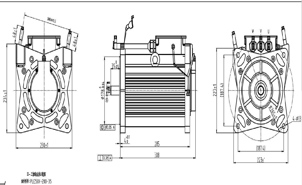
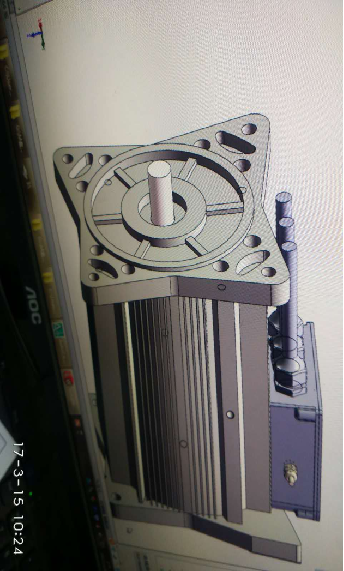
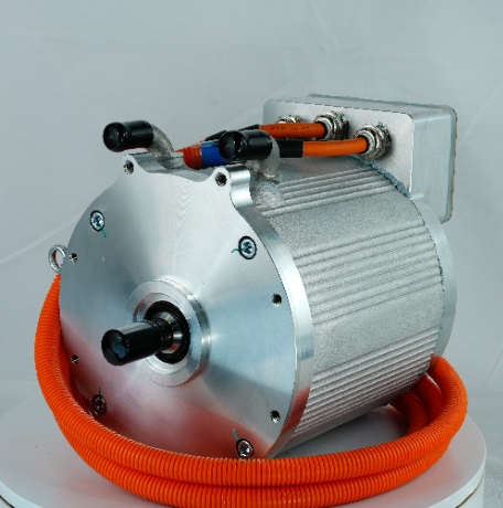
1. Motor appearance and structure
2. Motor technical parameters
|
project
|
Specification
|
Executive standard
|
|
|
type
|
Permanent Magnet Synchronous Motor
|
GB/T18488.1-2015
Motors and Controllers for Electric Vehicles Part 1 Specifications
GB/T18488.2-2015
Electric Motors and Controllers for Electric Vehicles Part 2 Test Methods
|
|
three-phase connection
|
Y type
|
|
rated power
|
15KW
|
|
Rated speed
|
3000r / min
|
|
Rated torque
|
47N.M
|
|
peak power
|
35KW
|
|
peak speed
|
6600r / min
|
|
peak torque
|
150N.M
|
|
Working temperature
|
-25℃~40℃
|
|
storage temperature
|
-40℃~85℃
|
|
quality
|
35kg±2
|
|
Insulation class
|
H
|
|
cooling method
|
Free cooling
|
3. Motor technical description
1. Motor installation method: This motor is a pure electric system drive motor. The drawings and the shape and structure of the motor are batch products of our company and are for reference only (the dimensions of the motor body and shaft extension)
2. Motor outlet method:
a. Three-phase power line: use a junction box, and lead the line out through a waterproof cable lock
b. Sensor port: The sensor port adopts Amphenol waterproof connector ;
3. Magnetic material: high temperature permanent magnet
4. The bearing adopts imported high protection grade products
5. Cooling method: natural cooling
6. The rotor position sensor is a resolver
7. Built-in stator temperature sensor: PT100
8. Motor installation size: 285 × 223 ( excluding shaft extension and junction box)
4. Motor analysis report
|
Rated voltage
|
144VDC
|
peak current
|
400A
|
|
rated power
|
15KW
|
peak power
|
35KW
|
|
Rated speed
|
3000rpm
|
peak speed
|
6600rpm
|
|
Rated torque
|
47Nm
|
peak torque
|
150 Nm
|
1 . Technical indicators
2. Finite element simulation
1 ) Peak torque simulation
Simulation conditions:
Speed: 2300 RPM Stator OD: 180 Number of Poles: 8
Coercivity: 870KA/M
According to the above simulation conditions, the results of various parameters are given:
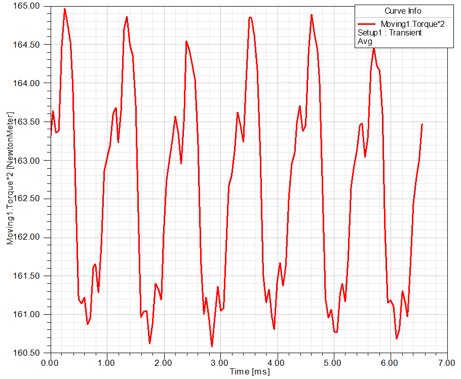
1 ) -1 torque curve
1 ) -2 wire back EMF curve
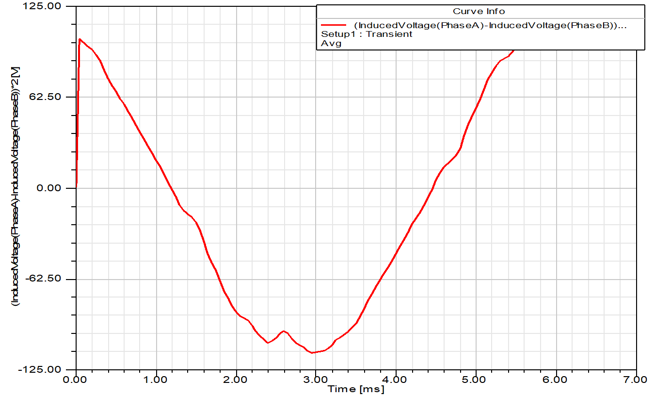
1) -3 Back EMF Fourier decomposition
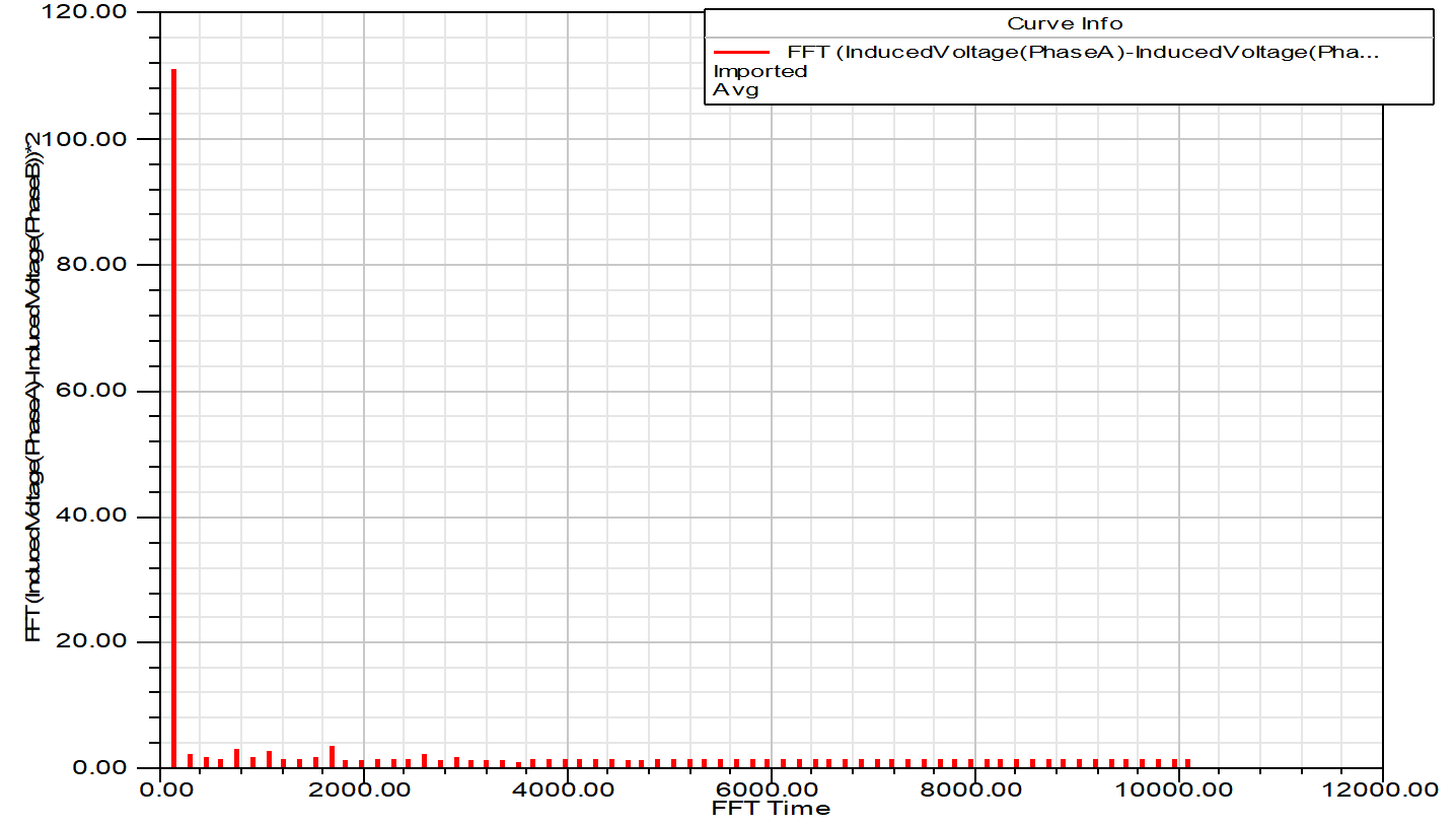
Peak torque simulation conclusion
According to the above analysis conclusion:
When the loading current is 400A , the peak torque of the motor is 162.5 Nm , and the peak power is 39.1KW . At this time, the peak value of the winding back EMF line voltage does not exceed 113V.
The motor meets peak power and peak torque requirements.
2) Peak speed simulation
Simulation conditions:
Speed: 6600 RPM Stator OD: 180 Number of Poles: 8
Coercivity: 870KA/M
According to the above simulation conditions, the results of various parameters of the quadrature axis current at 80A are given:
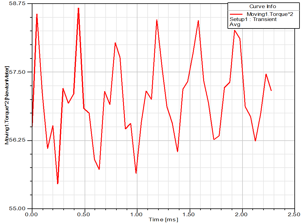
2 ) --1 torque curve
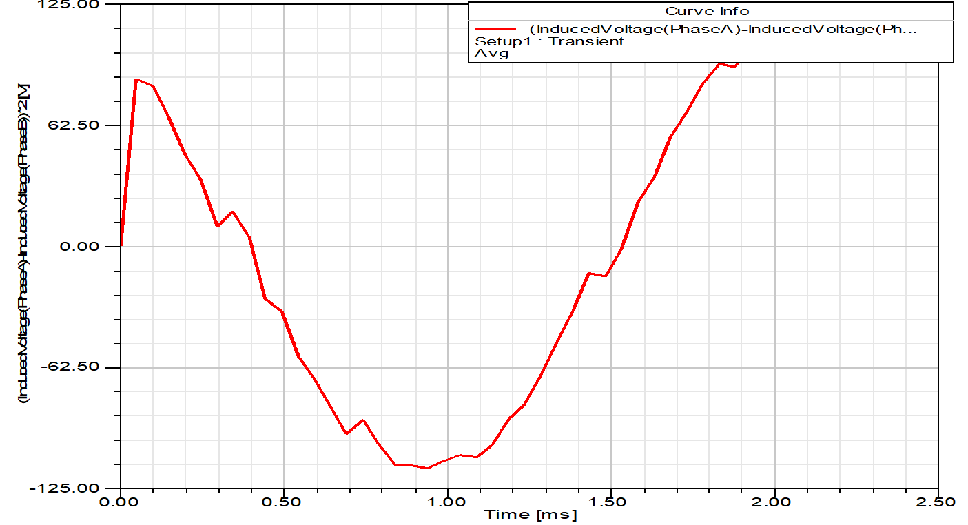
2)-2 line back EMF curve
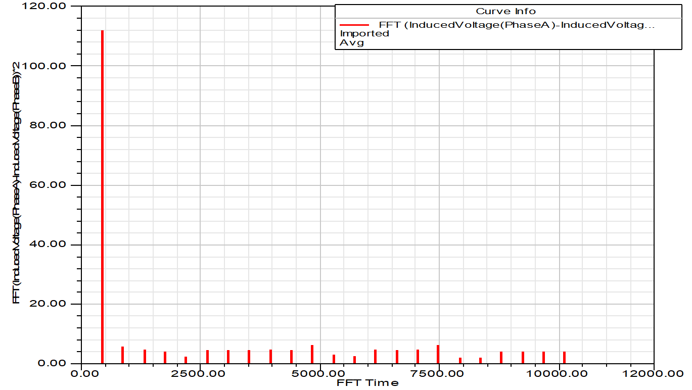
2) -3 Back EMF Fourier decomposition
Peak speed simulation conclusion
According to the above analysis conclusion:
When the current is loaded at 300A and the quadrature axis current is 80A , the torque is 57Nm . At this time, the peak value of the winding back-EMF line voltage is 112.5V , and the motor power is: 6.28 × 57 × 6600/60=39.4KW,
Meet the requirements of constant power expansion range.
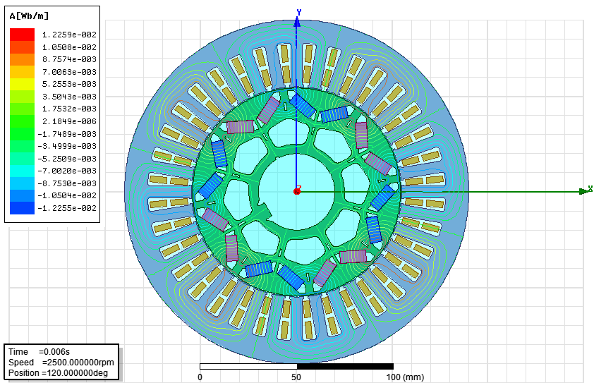
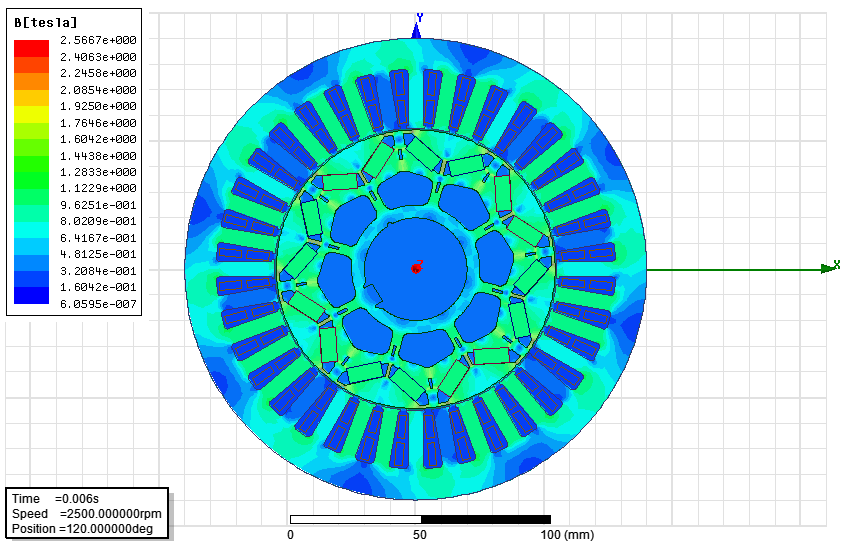
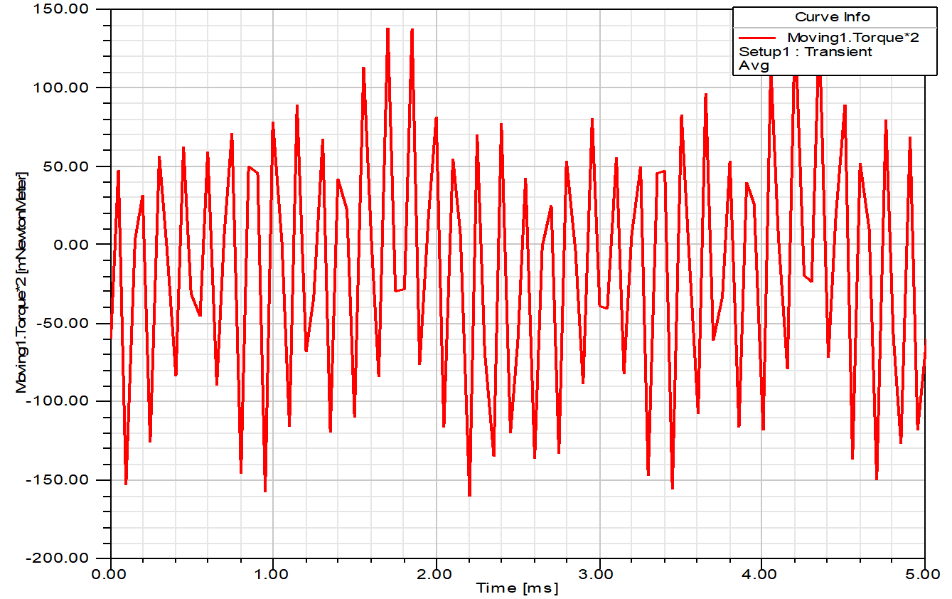
3) No-load rated speed simulation
Simulation conditions:
Speed: 3000 RPM Stator Outer Diameter: 180 Number of Poles: 8 Coercive Force: 970KA/M
According to the above simulation conditions, the results of various parameters are given:
3 ) 1 Magnetic field line analysis
3 ) -2 magnetic density distribution
3 ) -3 cogging torque curve
4) No-load peak speed simulation
Simulation conditions:
Speed: 6600 RPM Stator Outer Diameter: 180 Number of Poles: 8 Coercive Force: 970KA/M
According to the above simulation conditions, the results of various parameters are given:
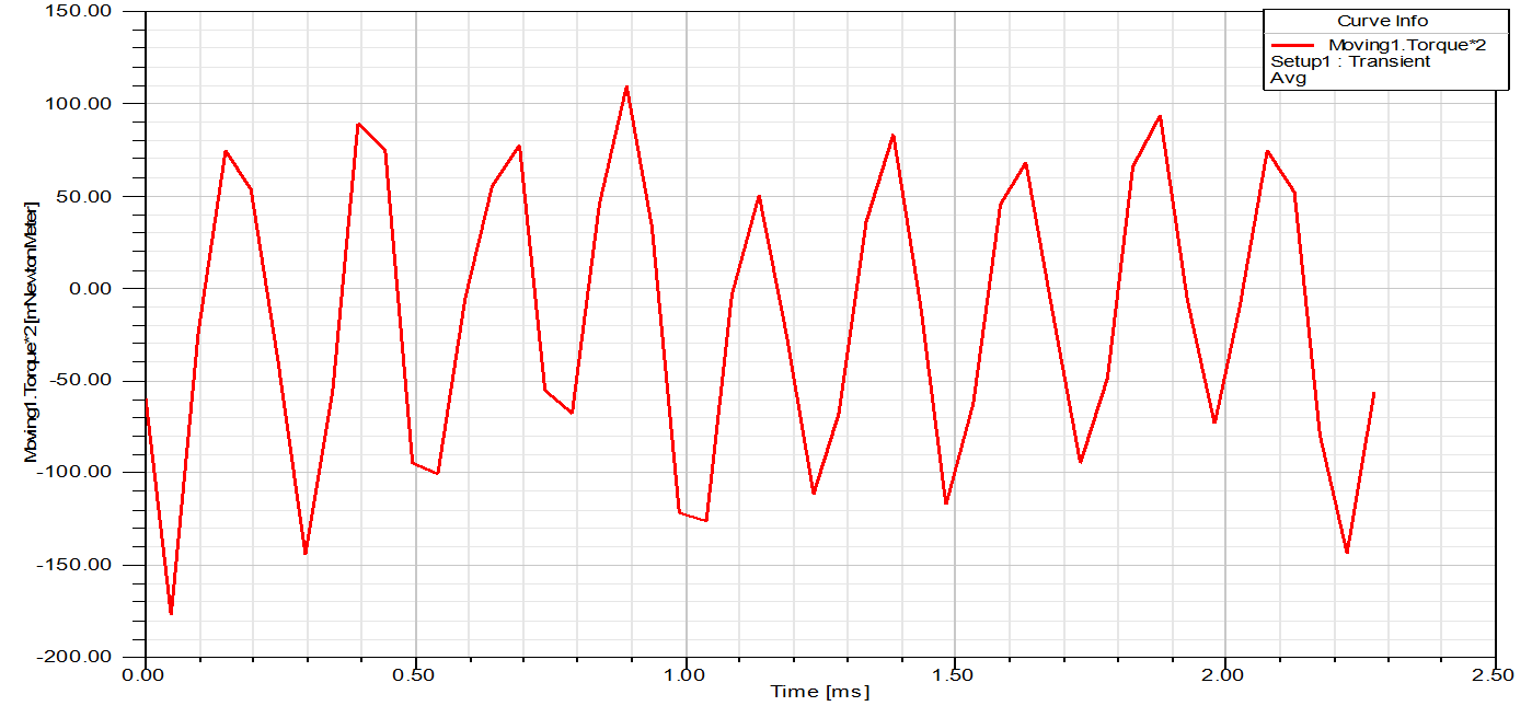
4 ) -1 cogging torque
4 ) -2 winding back EMF curve
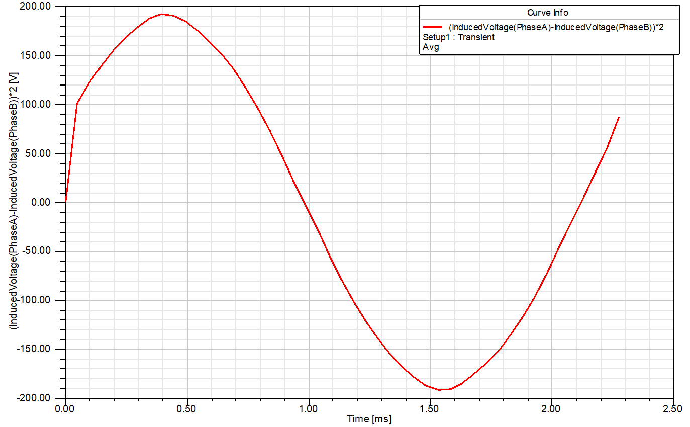
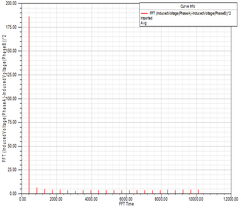
4 ) -3 Back EMF Fourier decomposition
The maximum value of the back EMF line voltage is 192.3V . Considering the parameters of the magnetic steel performance at 20 degrees in the simulation, the back EMF is about 185V in actual operation, and a MOS with a withstand voltage of 200V can be used, and the cost of the controller will be greatly reduced.
3. Rotor stress simulation
Simulation conditions: 1.2 times the peak speed
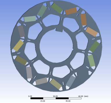
Simulation model
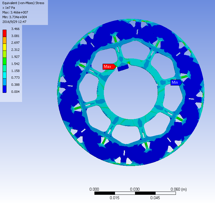
centrifugal stress
Safety factor
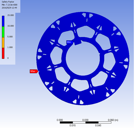
From the above analysis, it can be seen that at 1.2 times the peak speed of the motor, the stress at the magnetic isolation bridge is the largest, which is only 34.7Mpa, and the safety factor is large, so it can run safely.
Measured rated curve
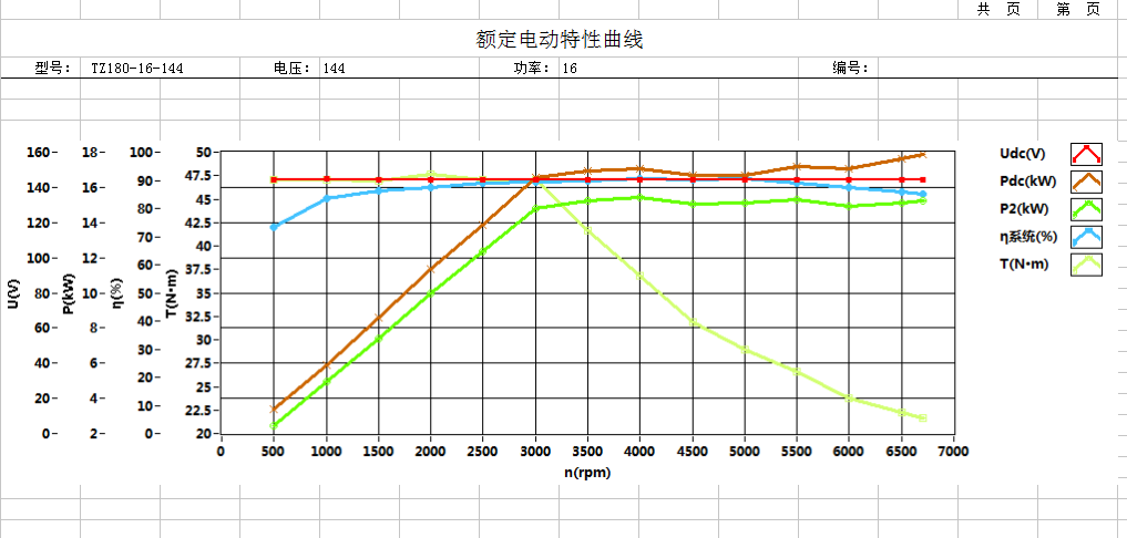
Rated electric characteristic curve conforms to simulation and theoretical design
actual data
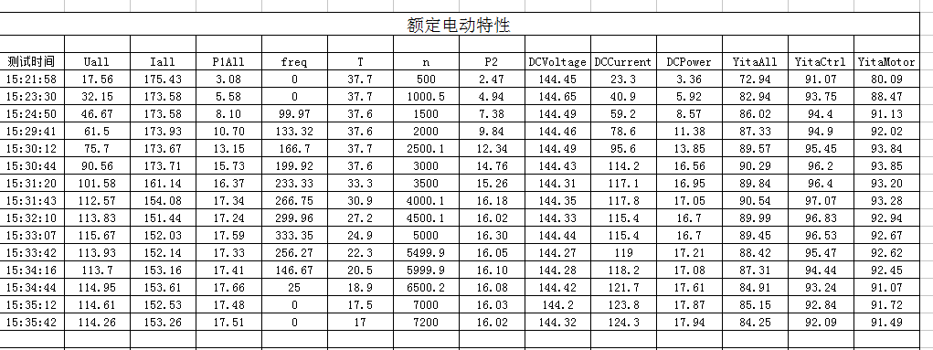
Measured rated data collection.
actual data
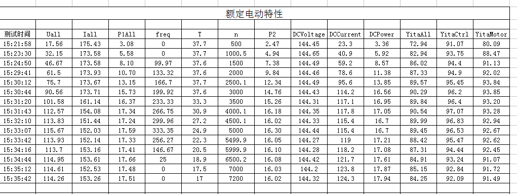
Measured rated data collection.
Feeding characteristic curve

efficiency map
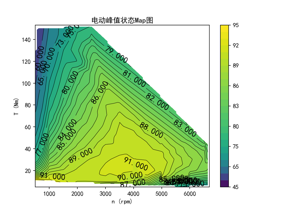
More than 80% of the high-efficiency area accounts for 82% , and the highest efficiency is 94.5% . The distribution of the high-efficiency area is in line with the ideal operating conditions of electric vehicles
Motor temperature rise curve

The measured temperature rise curve of the motor, the air temperature is 25 degrees, the full load still air flow test temperature is up to 105 degrees, and the actual temperature rise is 70K , which is well adapted to the vehicle operating environment
High-speed temperature rise data
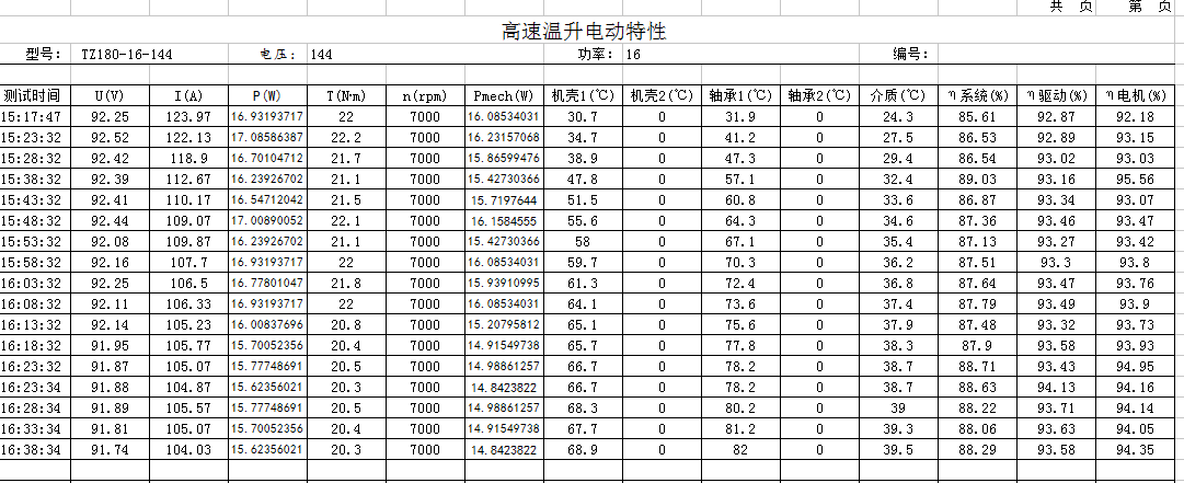
The measured high-speed temperature rise data of the motor is suitable for running at the highest speed of the vehicle
Motor compatible models
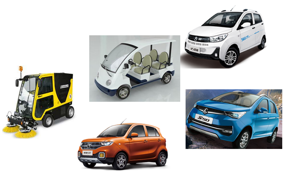
 Home
Home  EV KITS
 Electric Tricycle kits
 Four-wheelers kits
 EV Motor
 Oil Pump Motor
 EV Driving Motor
 EV and auto parts
 Conversion Kits
 XD Motor
 XD DC Motor
 XD AC Motor
 Industrial Motors
 Motor Drive Machines
 Knowhow
  About XD
 Company Profile
 Honor
Honor Factory Appearance
 XINDA Team
 Events
 Summit
 Clients Visit
 Exhibition
 Contact


 XINDA
XINDA