30KW144V AC asynchronous motor parameter
Motor code: YS210HS30144-YBE
-rated power: 30KW
-rated voltage: 144VDC
-rated speed: 3000r/min
-rated current: 258A
-rated torque: 95.5 N.m
-protection grade: IP66
-insulation grade: H
-work system: S2-60min
-application: electric tour car, electric trucks, electric logistic vehicles, electric commercial vehicles
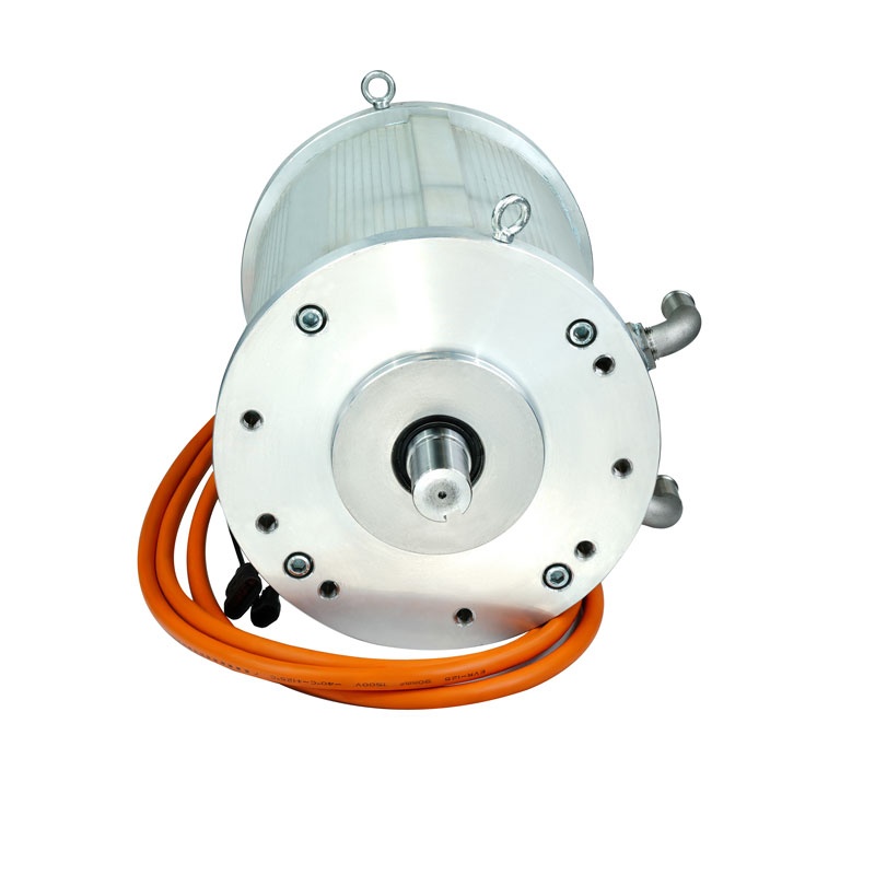
30KW144V AC asynchronous motor drawing

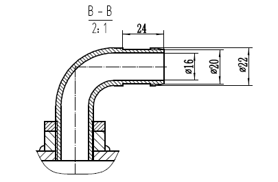
Technical requirement
1. All parts should be kept clean and intact before assembly; when installing the motor to tighten the threads, add thread locking and sealant, and tighten the torque in accordance with
the standards. Tighten crosswise, symmetrically, gradually and evenly, and the threads must be marked after tightening; during the assembly process, the stator and rotor air gaps
should be ensured to be uniform, without friction and abnormal noise, and no foreign matter should enter the inside of the motor; after assembly, the overall appearance of the
product is clean and free of dirt , no obvious defects, all labels are firmly in the correct position; turn it gently by hand, the motor should be light and free of jamming.
2. Facing the motor output shaft, when the letter sequence of the motor wire ends is the same as the power phase sequence, the motor rotation direction is clockwise.
3. Coat the outer surface of the motor shaft extension with anti-rust oil for anti-rust treatment.
4. When installing the oil seal, check whether the lip is damaged or deformed, whether the spring is falling off or rusty, and apply an appropriate amount of lubricating oil between the lips of
the oil seal and the outer surface of the shaft extension; when installing, it must be installed flat and not tilted. For specific operations, refer to the "Skeleton Oil Seal Installation Process Code".
5. Dimensional tolerances not noted shall be based on GB/T1804-m level, and geometric tolerances shall be based on GB/T1184-k level;
6. The lead wire of the speed sensor is 500±30mm long, and the lead wire of the temperature sensor is 500±30mm long.
7. Temperature sensor model: KTY84-150, resistance value at 20℃: 5442-6182.
The drive motor winding should be able to withstand the power frequency withstand voltage test of 1500VAC for the temperature sensor, the test time is lmin, and there should be no breakdown.
Leakage current is not greater than 5mA.
8. The water inlet and outlet of the motor are covered with rubber caps (manufacturer: Senrui Rubber, rubber cap number: 057831) to prevent dust when leaving the factory.
9. Safety test:
Definition of insulation resistance and withstand voltage of phase line pair chassis: cold insulation resistance is not less than 20M2 (DC1000V); withstand voltage is
1500VAC, 50Hz, 1min, and leakage current is not more than 10mA.
Stator coil inter-turn insulation impact withstand voltage test, test voltage peak value is 1800VDC, wave front is 0.5us, and there should be no breakdown
or flicker for 1-3s.
10. During debugging, it should operate flexibly, without stagnation or abnormal noise. During transportation, care should be taken to prevent collision and deformation.
11. There is no gap in the crimping of the speed sensor and temperature sensor connector pins at the wire inlet, there is no looseness in the wire compression part, and the
terminal pull-out force complies with QC/T 29106-2016 "Technical Conditions for Automobile Low-Voltage Wiring Harnesses" 4.4.6 Regulations, tensile test ≥110N;
12. The motor must meet the following standards:
GB/T 18488.1-2015 "Motors and Controllers for Electric Vehicles Part 1: Technical Conditions";
GB/T 18488.2-2015 "Motors and their controllers for electric vehicles - Part 2: Test methods";
GB/T 29307-2012 "Reliability test method of drive motor system for electric vehicles";
Environmental protection requirements comply with GB/T 30512-2014 "Requirements for Prohibited Substances in Automobiles".
Coupling drawing
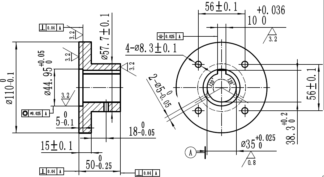
Technical requirement
1. Unindicated linear dimensional tolerances should comply with the blood level requirements of GB/T1804-2000;
2. The chamfer not marked is 1×45°;
3. After the processing is completed, remove the sharp corner burrs and blunt the sharp corners to R0.5;
4. Blackening treatment.
Link flange drawing (250KW Performance Test Dynamometer)
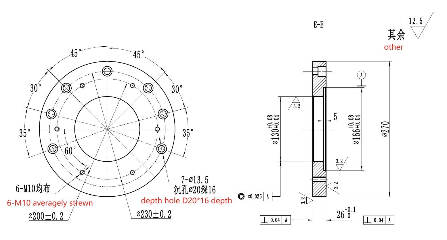
Technical requirement
1. All chamfers not marked are 1×45°.
2. The limit deviation of dimensions without tolerances is in accordance with GB/T1804-m.
3. Deburr after processing.
Coupling Drawing (250KW Performance Test Dynamometer)
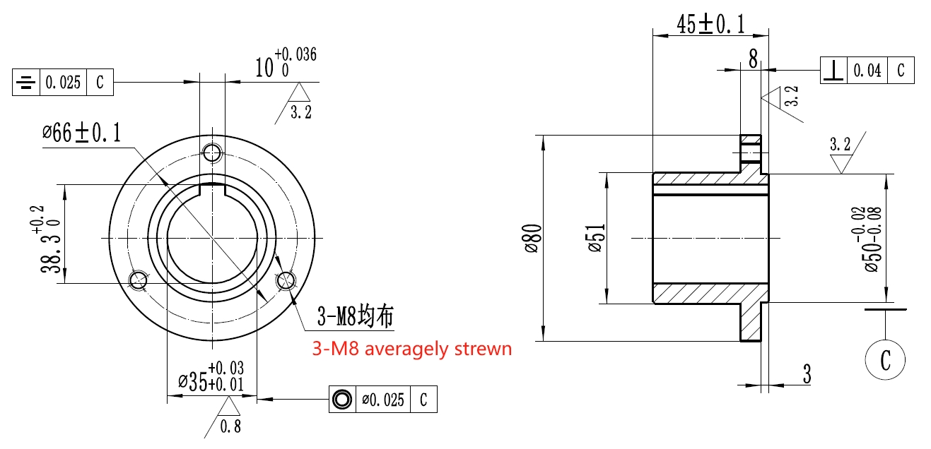
Technical requirement
1. Blank quenching and tempering treatment HRC23-28
2. Linear dimensional tolerances not noted shall comply with the m-level requirements of GB/T1804-2000
3. The chamfer not marked is 1×45°
4. Remove sharp corner burrs after processing is completed
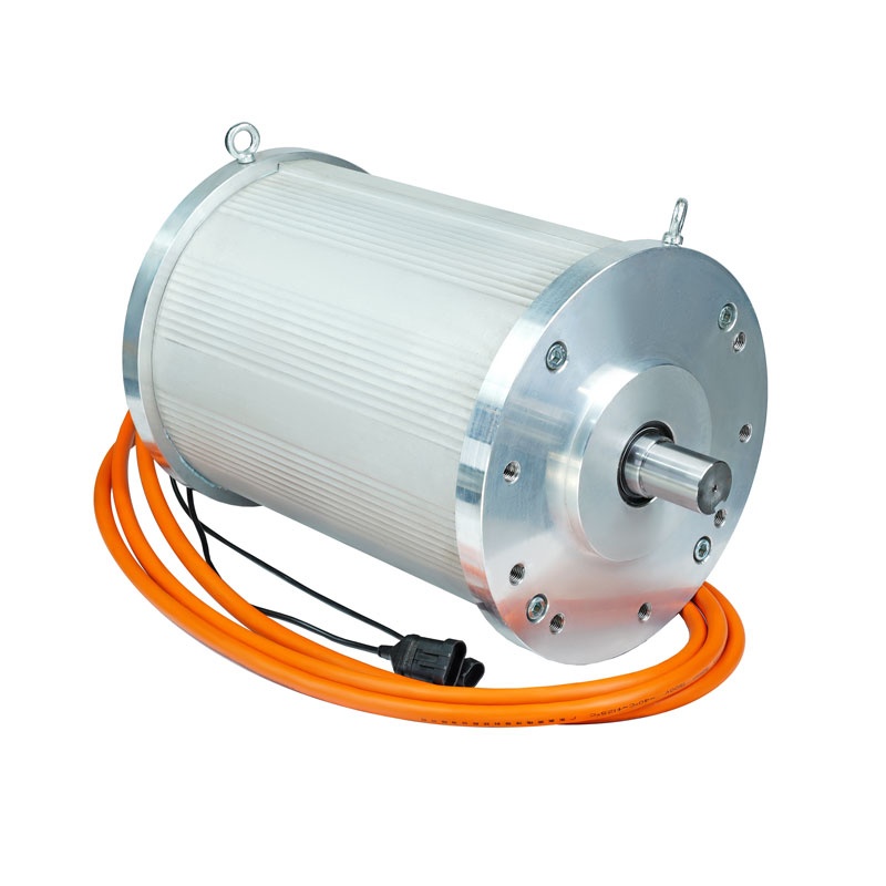
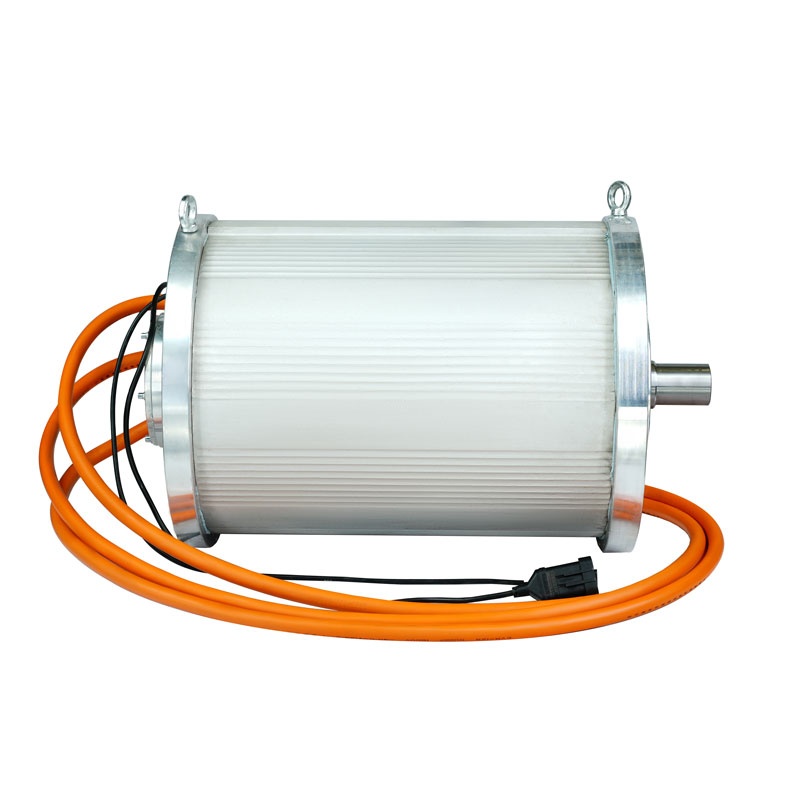
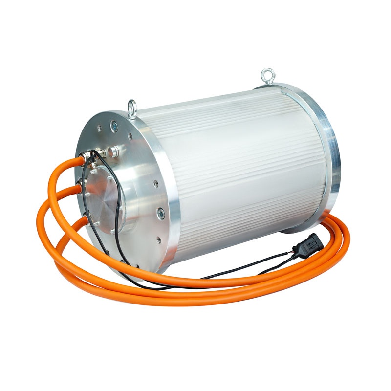
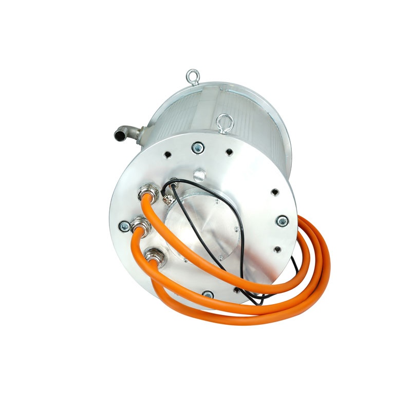
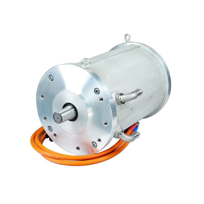
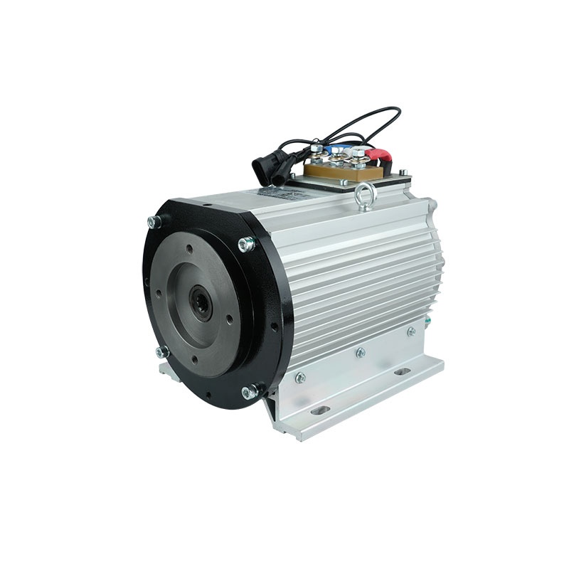
30KW144V AC asynchronous motor pictures
 Home
Home  EV KITS
 Electric Tricycle kits
 Four-wheelers kits
 EV Motor
 Oil Pump Motor
 EV Driving Motor
 EV and auto parts
 Conversion Kits
 XD Motor
 XD DC Motor
 XD AC Motor
 Industrial Motors
 Motor Drive Machines
 Knowhow
  About XD
 Company Profile
 Honor
Honor Factory Appearance
 XINDA Team
 Events
 Summit
 Clients Visit
 Exhibition
 Contact



 XINDA
XINDA