![]()
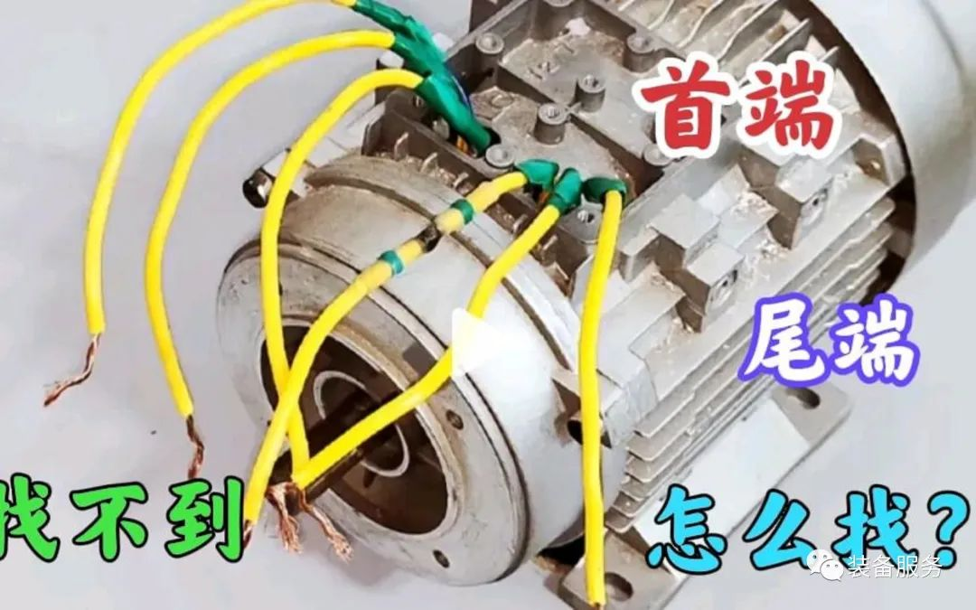
Generally, the head and end of the winding of the motor stator are led to the outlet board, and the symbols D1, D2, and D3 are used to represent the head end, and D4, D5, and D6 are used to represent the end. The six wire ends of the motor stator winding can be connected in a "Y" shape or "△" shape according to the regulations on the nameplate. However, in actual work, it is often encountered that the markings of the three sets of stator winding lead wires of the motor are lost or the beginning and end are unknown. In this case, the following methods can be used to determine the sentence.
1 Use the small light bulb and battery method
① First determine the two wire ends of the same phase winding. Use two dry batteries and a small light bulb in series, connect one end to any wire lead from the stator winding, and then connect the other end to the other five wire ends respectively. If the light bulb lights up when touching a certain lead wire end, it means The two wire terminals connected to the battery and the light bulb belong to the same group. Follow this method to find the two in-phase wire terminals of the other two phase groups and mark them one by one.② Connect any two phase windings and small light bulbs in series to form a circuit. Connect one end of the third phase winding to a battery in series, and touch the other line to the other pole of the battery. If the light bulb lights up (according to the transformer principle, the series connection The instantaneous induced potentials of the two-phase system are superimposed, so the bulb lights up), which indicates that the two-phase windings are connected in series, that is, the two wire ends connected to the bulb, one is the first end of the first wire Dl , the other end of the line is the end of the second phase D5. If the light bulb does not light up, it means that the instantaneous induced potential generated by the two-phase series windings is subtracted. Their magnitudes are equal and their directions are opposite, so that the total induced potential is zero. Therefore the light bulb does not light up. This shows that the two wire ends connected to the light bulb are the first ends of the two-phase windings D1 and D2 (or D4 and D5), and the first and last ends are marked.③ Connect the first and last phases of the first-phase winding and the third-phase group in series, and then use the above method to identify the first and last ends of the third-phase winding. Finally, mark the first and last ends of D1 to D6 for easy wiring.In the above method, it should be noted that the rated voltage of the bulb must match the battery voltage. Otherwise, the current may be too small and the bulb may not light up when it should, resulting in a misjudgment. Therefore, the wire ends of the two-phase series windings should be reversed. , test again. If the bulb does not light up twice, it means that the induced current is too small. Appropriately increase the number of batteries (increase the voltage) or replace a bulb with a smaller rated voltage. In the same way, 220V or 36V AC power supply and incandescent lamp can also be used to replace batteries and small light bulbs.However, in order to prevent excessive induced potential from burning out the bulb and winding, the bulb and the power supply should be swapped and connected in series to the winding, that is, the original single-phase winding (series connection to ground) is connected to the incandescent lamp, and the original two-phase winding is connected in series to the bulb. When switching to AC power supply, the judgment method is the same as above, but special attention should be paid to safety. At the same time, it should be noted that after switching to AC power supply, the time for connecting the winding coil should be shortened as much as possible to avoid overheating of the coil and affecting its insulation.2 Use the multimeter and battery method① Use a multimeter to replace the battery and small light bulb, and measure the two wire ends of each phase winding. The two wire terminals with the smallest resistance value are the wire terminals of one phase winding.② Switch the multimeter selector switch to the three-measurement DC current range (or DC voltage range is also acceptable). The range can be smaller, so that the pointer deflection is obvious. Mark the two wires of any group of windings with the first end D1 and the end D4 and connect them to the multimeter. Specify that the first end D1 is connected to the "-" terminal of the multimeter, and the end D4 is connected to the "+" terminal of the meter. "Serve it.Then connect one end of the wire wound by the other phase to the negative electrode of the battery, and touch the other end to the positive electrode of the battery. At the same time, pay attention to the instantaneous deflection direction of the watch hand. If the watch hand is moving (turning to the right), it is in contact with the battery positive electrode. The end of the wire that is touching is the first end, and the end of the wire that is connected to the negative electrode of the battery is the end. Mark the first and end ends D2 and D5. If the pointer of the multimeter instantly shifts in the opposite direction (turn to the left), the beginning and end of the phase winding will be exactly opposite to the above.③With the connection between the multimeter and the winding unchanged, use the same method as above to identify the beginning and end of the third phase winding. The principle of this method is also to utilize the electromagnetic induction principle of the transformer. It should be noted that the deflection direction of the multimeter pointer is observed at the moment when the battery is connected, not the deflection change of the multimeter pointer at the moment when the battery winding is disconnected.3 Utilize the residual magnetism of the motor rotor and the multimeter method① Use a multimeter to identify the two wire ends of the same phase winding. The method is the same as before.② Connect the three-phase windings together in parallel, use the milliamp range or low voltage range of the multimeter to measure the current or voltage at both ends of the parallel windings, and rotate the rotor at the same time. If the multimeter pointer does not move, it means that it is the three first ends of the stator winding ( D1, D2, D3) are connected in parallel, and the three terminals (D4, D5, D6) are connected in parallel. If the multimeter pointer rotates, it means that the head end phase is not in parallel with the end phase phase. At this time, each phase winding should be adjusted one phase at a time and observe the condition of the meter needle until the multimeter pointer does not move. Then the head and end phase can be done. mark.This method is based on the directional relationship of the induced electromotive force generated in the stator winding by the residual magnetism in the rotor. Therefore, the motor rotor must have residual magnetism, that is, it must be a motor that has been running or passed electricity.


 XINDA
XINDA