Comparison of domestic and foreign motor manufacturing processes
Abstract : This article introduces the main production processes of overseas motors, and conducts comparative analysis, which can be used as a reference for motor manufacturers.
1. Punching process
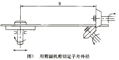
After punching positioning holes on the square silicon steel sheet , cut the outer diameter of the stator punching sheet on a circular shearing machine. This method has high efficiency, can cut a wide range of diameters, and has high punching precision (roundness, coaxiality); the tool structure is simple, and it is easy to sharpen, assemble and disassemble (see Figure 1).

In China, however, a blanking die is still required for punching pieces larger than φ520mm. The production difficulty and cost of large-diameter blanking die are relatively high, and the adaptability is single, and its maintenance cost is also high.
2. Stator core process
The stator core lamination adopts the cylindrical tire structure of the whole cylinder, commonly known as "dead tire". The roughness of the cylindrical working surface is relatively high, generally above 3.2μm, and the coaxiality with the axis is generally below φ0.05mm. There is also a keyway processed on the cylindrical surface. When laminating, a long key is inserted in the groove. Match the notch width of the punching plate to ensure that the stator slots are not skewed. After lamination, use the center holes at both ends of the mold mandrel to position, and turn the outer circle of the iron core to the required size on a lathe. The machining allowance is generally 0.5-1mm (diameter).
Its purpose is twofold:
One is to further improve the coaxiality of the "active dimension" of the inner and outer diameters of the iron core.
The second is to effectively improve the contact condition between the iron core and the machine base, so as to improve the heat conduction and heat dissipation of the machine base, reduce the operating temperature of the motor, and prolong the thermal aging life of the insulation. However, in China, the tire structure is generally used. When stacking the tires, the tires are not tightened, and the film is easy to install, and the tires are only tightened when pressurized. The outer circle of the iron core is generally not processed.
3. The belt winding is fixed on the machine base
The motors above H355 all use the shrink-fit stator technology, some hang the stator into the machine frame, and some crane seat cover the stator, generally the former is more common. Heat the base to 120-150°C and keep it warm for about 3 hours. This method can prevent the winding stator from being crushed, and does not require a large-scale press.
4. Rotor
The cast aluminum rotors of small and medium-sized motors mostly adopt the horizontal high-pressure aluminum casting process, and the aluminum is fed from the inner side of the rotor end ring. The end face of the rotor is completely formed by the mold, without process cut marks, very smooth, and the equipment has a high degree of automation. Smaller rotors can be die cast 3 at a time.
The way to realize the inclination of the copper bar rotor groove is to process the lamination keyway on the shaft to have a certain angle with the axis (Fig. 2). When stacking , install long keys in the key groove, and then install the slices on the shaft, and the slope of the groove is formed during stacking. It should be noted here that the inclination of the shaft keyway is the converted value of the inclination of the rotor slot.

Kz=Kp(Rz/Rp)
In the formula: Rz, Kz——shaft radius and shaft keyway inclination
Rp, Kp——Rotor punching radius and rotor slot slope
This slot slope is an approximate value, and the rotor slot has a very slight spiral, but practice has proved that it can meet the design and process requirements, and does not require special tooling and equipment. It is a "zero cost" method.
When inserting copper guide bars, put the rotor on the roller frame. First, insert the guide bars with a hand-held guide bar every other slot, push them in about 100mm, insert 3-5 bars in a row, and then drive them in with a pneumatic tool. At this time, the head of the guide bar is covered with a pad that fully matches the head, so as to prevent the impact force of the pneumatic tool from damaging the head of the guide bar. After inserting half of the slots of the rotor, insert the other half of the slots.
This method is different from slot-by-slot insertion. The condition of the guide bars in the rotor slots is much better and the uniformity is good.
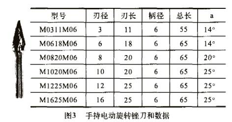
After the outer circle of the copper guide bar rotor is fine-turned, the notches are chipped and blocked, and the hand-held electric rotary file (Figure 3) is used to clean them. The efficiency is high, and the notches are neat and the chamfers are obvious. Some rotors do not have an outer circle, because the rotor punch has left an air gap.

The dynamic balance of the rotor is generally carried out at the rated speed. The dynamic balancing machine is intelligent, with a protective cover.
5. Double cooling heat dissipation structure of the machine base
In some occasions where the power is large and the volume is limited, the motor generally adopts a "wind-water" cooling structure. The machine base has a three-layer structure, and the inner two layers are water circulation cooling channels. The outer layer forms an air duct, and the heat flow in the inner cavity of the motor enters the air duct, which is not only cooled by water, but also dissipated through the outer cover tube.
6. Slip ring structure
The slip ring set of wound rotor has three characteristics:
(1) There is a spiral groove on the slip ring, which is used to smooth the brush and keep in good contact with the slip ring.
(2) The outer end of the slip ring group is equipped with a large-diameter fan for cooling and cleaning.
(3) The rotor lead terminal is sealed with a dust cover to isolate it from brush dust to prevent failure caused by creepage.

7. Motor assembly
The assembly in foreign countries is extremely serious, and the parts used for assembly must be visually inspected, and they are used only after they are satisfied. The workers of the required inspection items are consciously and strictly abide by it, and the records are very serious. Rather than what we always think, the parts provided by the previous process are all qualified, and it is enough to just use them during assembly. In fact, we confuse "qualified" with "flawless". The following operations and self-inspection items need to be paid attention to:
(1) If there is paint peeling or unevenness on the primed surface of the parts, it should be repainted.
(2) If the bolt is not screwed in smoothly, it is necessary to ream the screw hole once with a tap.
(3) If minor scratches are found on the non-important surface of the parts, they must be ground.
( 4 ) No matter how big the bolts and nuts are, there are standards for tightening torque (Nm).
( 5 ) For the bearing structure with oil discharge, the lubricating grease must be filled up.


 XINDA
XINDA