


Core components of new energy vehicles - understanding electronically controlled IGBT modules
The current module system of new energy vehicles is composed of many parts, such as battery, VCU, BSM, motor, etc., but these are relatively mature products. The internal emphasis is on the motor drive part, which is the core component of the motor drive part, IGBT (Insulated Gate Bipolar Transistor insulated gate bipolar transistor chip).
According to the data from the Passenger Association, the domestic retail penetration rate of new energy vehicles will be 27.4% in June 2022, and the EU announced on June 29, 2022 that the 27 EU member states have initially reached an agreement that Europe will ban the sale of fuel vehicles in 2035 . The market is getting more and more prosperous, and at the same time, the newly released new energy models in China are also blooming. Whether it is ordinary consumers, practitioners in the new energy vehicle industry, or investors in the primary and secondary markets, they are gradually paying more attention to the research of some core components of new energy vehicles, especially the power device IGBT module. Today, I will use the form of questions and answers Let me explain it to you, hoping to help you with a more popular explanation.
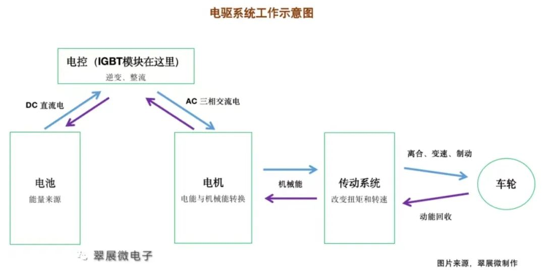
To understand the IGBT module, you must first understand the electric drive system of new energy vehicles. First, summarize how the electric drive system works in one sentence: When driving a new energy vehicle, the motor controller converts the direct current (DC) released by the power battery into Alternating current (AC) (this process is inverter) makes the drive motor work, the motor converts electrical energy into mechanical energy, and then makes the wheels of the car run through the transmission system (mainly the reducer). Conversely, the process of converting and storing the mechanical energy of the wheels into the battery is kinetic energy recovery.
1. What are "three-electric system" and "electric drive system"?
The three-electric system, namely power battery (referred to as battery), driving motor (referred to as motor), and motor controller (referred to as electronic control), are also regarded as three major components, which together account for more than 70% of the total cost of new energy vehicles. It is the core component that determines the sports performance of the vehicle.
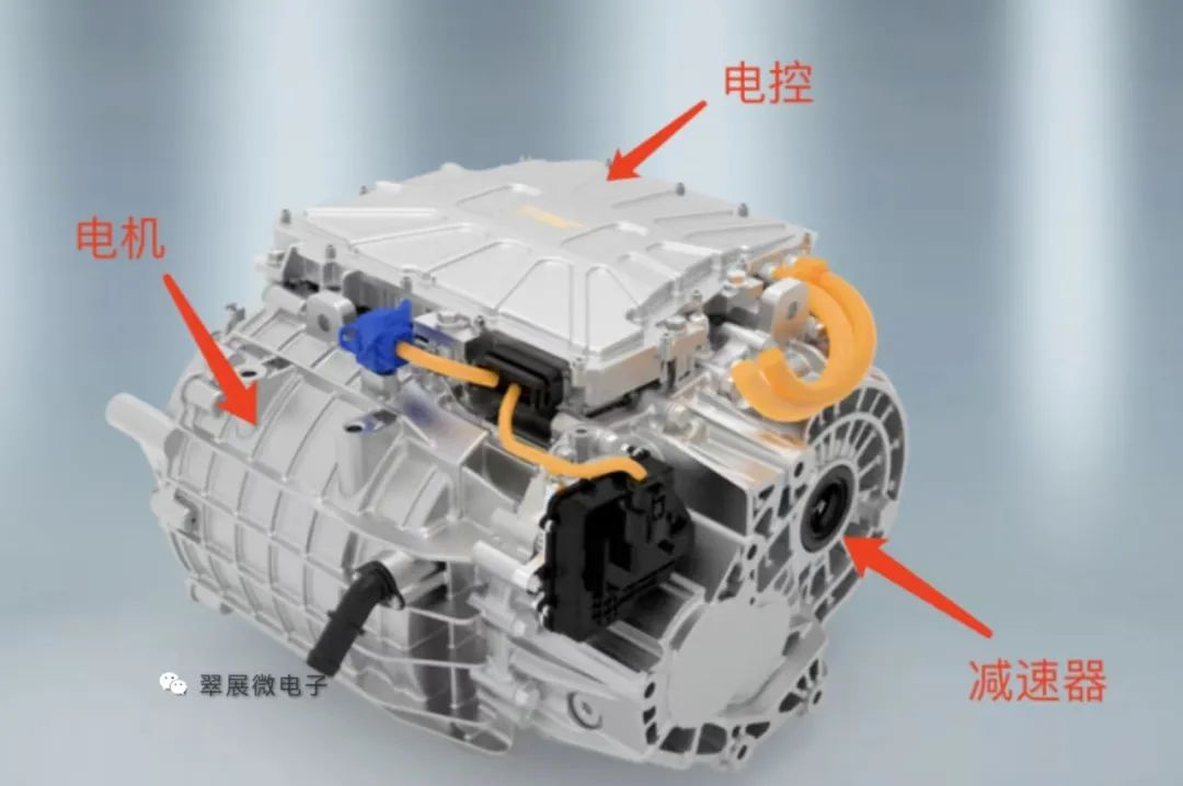
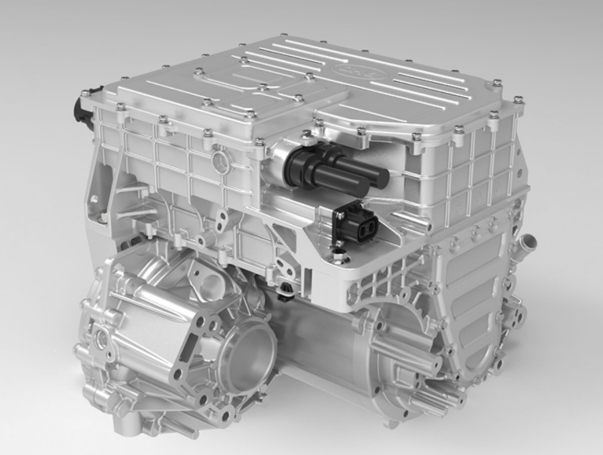
For the electric drive system, we generally simply refer to the motor, electric control, and reducer as the electric drive system.
But strictly speaking, according to Jinjing Electric’s prospectus, the electric drive system includes three major assemblies: drive motor assembly (converts the electric energy of the power battery into rotating mechanical energy, which is the source of output power), controller assembly ( Based on the hardware and software design of the power semiconductor, the working state of the driving motor is controlled in real time, and other control functions are continuously enriched), the transmission assembly (reducing the output speed through the gear set and increasing the output torque to ensure the continuous operation of the electric drive system at high efficiency interval).
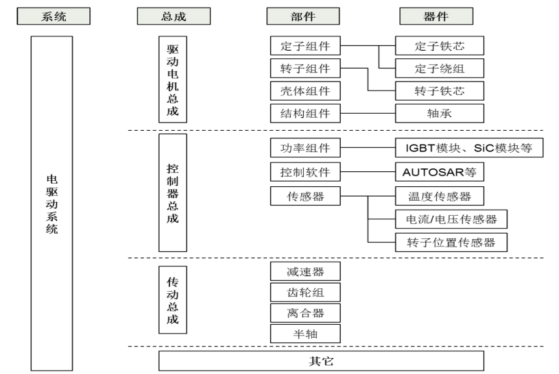
Figure: Schematic diagram of electric drive system
Image source: Jinjing Electric’s prospectus
2. What is "all-in-one electric drive system"?
At the beginning, the motor, electric control, and reducer were all independent components, but with the advancement of technology, we combined these three parts into one component, which became a "three-in-one electric drive". The main purpose of integration is to save space, reduce weight, improve performance, and reduce costs.
Source: Juyi Technology official website, Cuizhan micro-organization
At present, the "eight-in-one electric powertrain" of BYD's Fudi Power is highly integrated in the market. This eight-in-one electric drive system integrates a drive motor, a motor controller, a reducer, an on-board charger, a DC Inverter, distribution box, vehicle controller, battery manager.
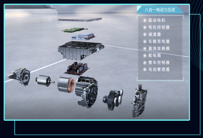
Source: Fudi Power
Of course, it does not mean that the higher the integration level, the better. There are issues such as heat dissipation structure design, system stability, and production process maturity that need to be solved. For consumers, the cost of later maintenance is also a big problem. Therefore, how to choose the all-in-one electric drive system needs to be comprehensive.
3. How does the IGBT module work?
In the electronic control module, the IGBT module is the core component of the inverter, and its working principle is summarized: through the non-on and off semiconductor characteristics, without considering the transition process and parasitic effects, we regard a single IGBT chip as an ideal switch. We built a parallel-series structure of several IGBT chip units inside the module. When the DC power passes through the module, the direction and frequency of the current flow can be changed by the rapid disconnection of different switch combinations, so as to output the AC power we want.
The role of the IGBT module in the electric drive system is mentioned above. Let's expand to see the structure of the IGBT module in detail.
4. What does the actual IGBT module look like?
The standard packaging form of the IGBT module is a flat rectangular parallelepiped. The figure below shows the perspective from the top of the HP1 module. The outermost white part is a plastic shell, and the bottom is a metal base plate (usually copper material) for heat conduction and heat dissipation. It can be seen that there are many terminals and pins outside the module, each with its own function:
1 is DC positive, 2 is DC negative; 3, 4, 5 are the U, V, W interfaces of the three-phase AC; 6, 25, 22 are the signal terminals of the collector, 7, 9, 11, 13, 15, 17 8, 10, 12, 14, 16, 18 are emitter signal terminals; 19 are DC negative signal terminals; 23, 24 are NTC thermistor terminals.
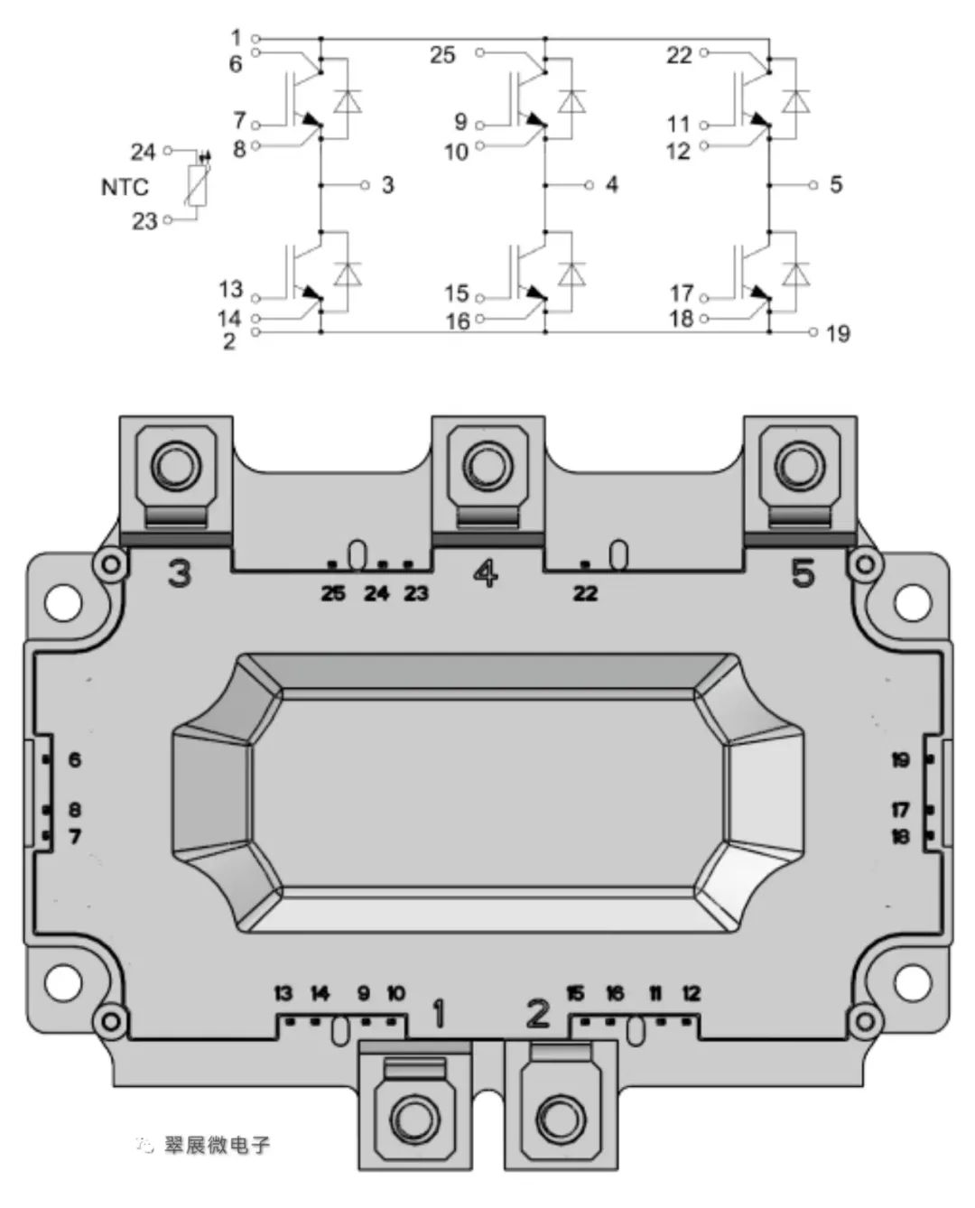
Source: Equivalent circuit diagram of HP1 module
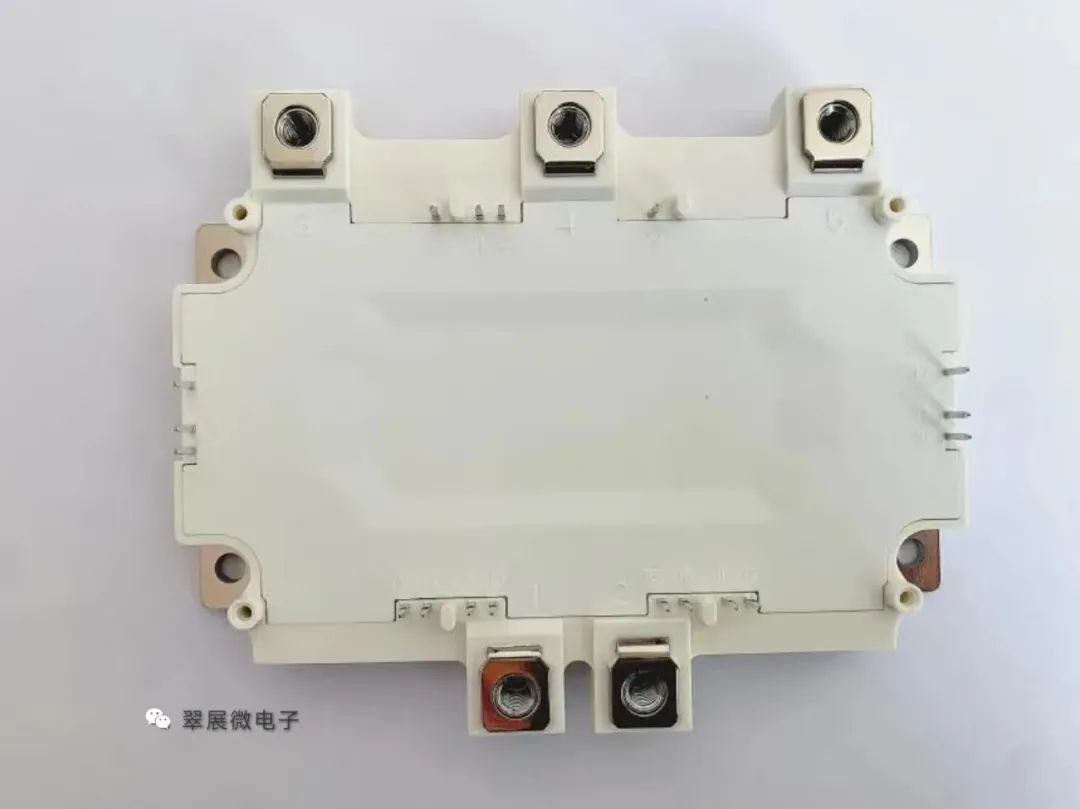
Figure: Equivalent circuit diagram of HP1 module
Source: Cuizhanwei
5. What is the basic topology of the IGBT?
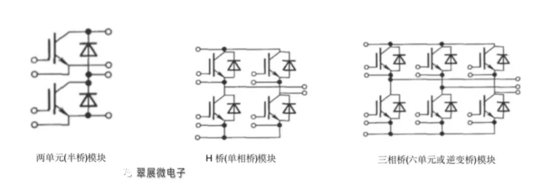
Figure: IGBT module basic circuit topology
Source: Cuizhanwei
As shown in the figure above, in the IGBT module/single tube, the first unit is generally referred to as an IGBT single tube, the second unit is a single bridge arm (half bridge), the fourth unit is an H bridge (single-phase bridge), and the sixth unit is a three-phase bridge. (full bridge), seven units are generally six units + a braking unit, and eight units are generally six units + braking unit + pre-charging unit.
A unit consists of 1 pair, 2 pairs or 3 pairs of FRD+IGBT. Among them, one pair can be 1 FRD+1 IGBT, or 1 FRD+2 IGBT, etc.
The specific object can refer to the figure below, which is a 6-unit IGBT module.
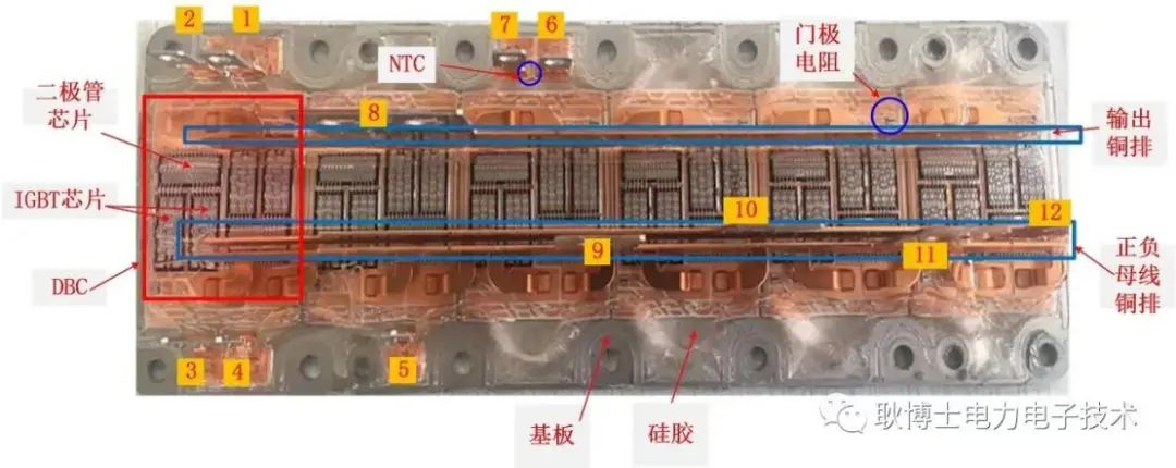
Figure: Infineon Primepack IGBT module
Source: "Dr. Geng Power Electronics Technology" public account
6. What is the production process of IGBT module?
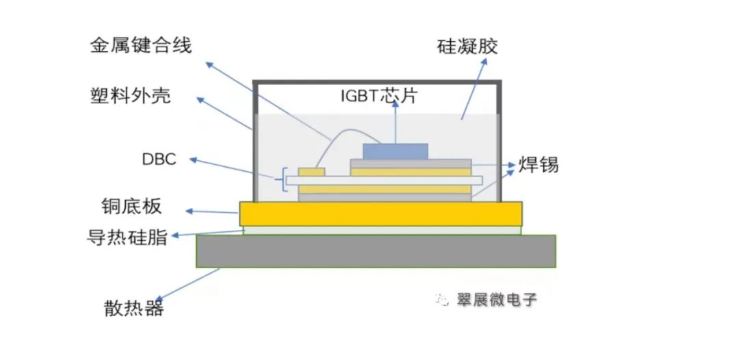
Figure: Cross section of IGBT standard package structure
Source: Cuizhanwei
As shown in the figure above, you can see the interface of the cross-section of the IGBT module. The basic structure of the modules in the current shell sealing process is not much different. The process of IGBT module packaging is roughly as follows: patch→vacuum reflow soldering→ultrasonic cleaning→X-ray defect detection→wire bonding→static testing→secondary welding→shell filling and curing→terminal forming→functional testing (dynamic testing , insulation test, reverse bias test)
For patching, firstly patch each die on the IGBT wafer to the DBC. DBC is a copper-clad ceramic substrate, with ceramics in the middle and copper-clad on both sides. DBC is similar to PCB for electrical conductivity and electrical isolation. Commonly used ceramic insulating materials are alumina (Al2O3) and aluminum nitride (AlN);
Vacuum welding, the die and DBC are fixed by vacuum welding after patching, and the general solder is tin sheet or solder paste;
X-ray void detection needs to detect the air bubbles that appear during the connection process, that is, voids. The existence of voids will seriously affect the thermal resistance and heat dissipation efficiency of the device, resulting in problems such as overheating, burnout, and explosion. General automotive IGBT modules require a void rate of less than 1%;
Next is the wire bonding process, which uses metal wires to bond die and DBC. The most used is aluminum wire, and other commonly used ones include copper wire, copper strip, and aluminum strip;
There will be a series of appearance inspections and static tests in the middle, and modules with problems in the process will be scrapped directly;
Repeat the above process to weld and bond the DBC to the copper base plate, and then perform the processes of glue filling, sealing, and laser coding;
The final functional test will be done before leaving the factory, including dynamic test of electrical performance, insulation test, reverse bias test and so on.
7. What are the common packaging types of automotive IGBT modules?
Econodual series half-bridge package, mainly used in commercial vehicles, the main specifications are 1200V/450A, 1200V/600A, etc.;
HP1 full-bridge package, mainly used in small and medium power vehicles, including some A-class vehicles, most of A0, A00 vehicles, the peak power is generally within 70kW, the model is mainly 650V400A, other specifications such as 750V300A, 750V400A, 750V550A, etc. ;
HPD full-bridge package, used in medium and high-power vehicles, most A-class vehicles and above, with 750V820A specifications occupying the mainstream of the market, other specifications such as 750V550A, etc.;
DC6 full-bridge package, based on the UVW three-phase full-bridge integral package solution, has the characteristics of compact package, high power density, and good heat dissipation performance;
TO247 single-tube parallel connection, there are also a small number of electronic control system solutions using TO247 single-tube package on the market. There are two main advantages of using the single-tube parallel scheme: ①The single-tube scheme can realize flexible line design, and the corresponding single-tube parallel connection can be used for as much current as is needed, so the cost also has certain advantages ; The module is easy to solve. However, there are still some difficulties to be solved when using single-tube parallel connection: ① It is difficult to share current and balance between each parallel-connected single-tube, and it is difficult to guarantee consistency, such as realizing simultaneous breaking, the same current, temperature, etc.; ② The customer's system design and process are very difficult; ③There are many interfaces, and the requirements for the production line are very high.
8. What tests and verifications are required for automotive IGBT modules?
Automotive IGBT modules have significantly higher requirements on product performance and quality than those in the consumer and industrial control fields. Therefore, automotive IGBT module certification has become the most important barrier in the automotive IGBT module market. Generally speaking, automotive IGBTs require a model introduction cycle of about 2 years. .
The test standards for automotive IGBT modules mainly refer to AEC-Q101 and AQG-324. At the same time, car companies will put forward corresponding requirements according to the characteristics of their own models. The main test methods include: parameter test, ESD test, insulation withstand voltage, mechanical vibration, mechanical shock, High temperature aging, low temperature aging, temperature cycle, temperature shock, UHAST (high temperature and high humidity unbiased), HTRB (high temperature reverse bias), HTGB (high temperature bias removal), H3TRB/HAST (high temperature and high humidity reverse bias), power cycle, Solderability.
Among them, the endurance test represented by power cycle and temperature cycle has extremely strict requirements. For example, the number of power cycles may vary from tens of thousands to hundreds of thousands of times. The main purpose is to test the durability of mechanical connection layers such as bonding wires and solder layers. The failure mechanism during the test is mainly that the thermal expansion coefficients of the chip, bonding wire, DBC, solder, etc. are inconsistent, resulting in the bonding wire falling off, breaking, chip soldering layer separation, and solder aging.
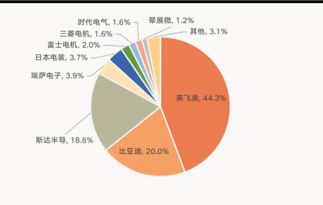
With the rapid development of the domestic new energy automobile industry, the upstream of the industry chain has gradually completed domestic substitution, and even led the world trend, such as vehicle brands, power batteries, battery materials, etc. have already moved forward. The automotive electronically controlled IGBT module is the core power device of new energy vehicles. It has been monopolized by foreign suppliers such as Infineon, ON Semiconductor, Semikron, and Mitsubishi Electric before. The rise of domestic suppliers such as CRRC Times, Silan Micro, and Cuizhan Micro has now been able to meet domestic demand to a certain extent. I believe that in the near future, domestic automotive semiconductor companies will become bigger and stronger!
Source: Automotive Electronic Controlled IGBT Module Market Conditions Thermal Management Technology
—END—
 XINDA
XINDA