


Detailed explanation of Ansys Maxwell RMxprt motor module classification
Three-Phase Induction Motors ( three-phase asynchronous motor ):
For a three-phase asynchronous motor, the stator windings (with sinusoidal spatial distribution and p-poles) are connected to a three-phase symmetrical voltage supply to generate a rotating magnetic field. The rotor winding is usually a squirrel-cage winding, and the rotor coil is cut in the rotating magnetic field to generate current, which in turn generates a second rotating magnetic field. Two rotating magnetic fields generate a synthetic rotating magnetic field in the air gap of the motor. The synthetic rotating magnetic field in the air gap interacts with the rotor coil current to generate electromagnetic torque, and the electromagnetic torque acts on the rotor along the direction of the magnetic field rotation in the air gap.
Single-Phase Induction Motors ( single-phase asynchronous motor ):
The structure of a single-phase asynchronous motor is similar in structure to a multi-phase squirrel-cage asynchronous motor, the main difference is the stator winding, which consists of a main winding and an auxiliary winding, these shafts are displaced by 90 degrees in space, to generate the starting rotation moment, the currents in the two windings must have a phase difference. Usually a capacitor is connected in series with the auxiliary winding, so that the auxiliary winding current is forced to lead 90 degrees different from the main winding current. Of course, two parallel capacitors can also be used, one for starting and one for running, so that both starting performance and obtain operational performance.
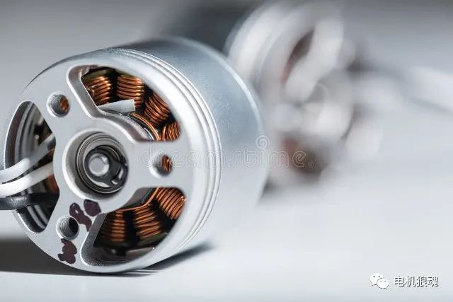
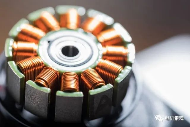
Brushless Permanent-Magnet DC Motors (Brushless Permanent-Magnet DC Motor):
The stator of the brushless permanent magnet DC motor is equipped with multi-phase windings, connected to the DC bus through the switching circuit, and the switching sequence is controlled to synchronize the position of the rotor, so the stator generates a rotating magnetic field. The rotor is fitted with permanent magnets forming a structure with the same number of poles at the stator, and the stator switches are like the commutator in a classic DC motor. In a brushless permanent magnet DC motor (BLDC), the armature current is precisely commutated according to the rotor position, and the rotor position signal can be obtained from a position sensor or an induced voltage from a sensorless control system.
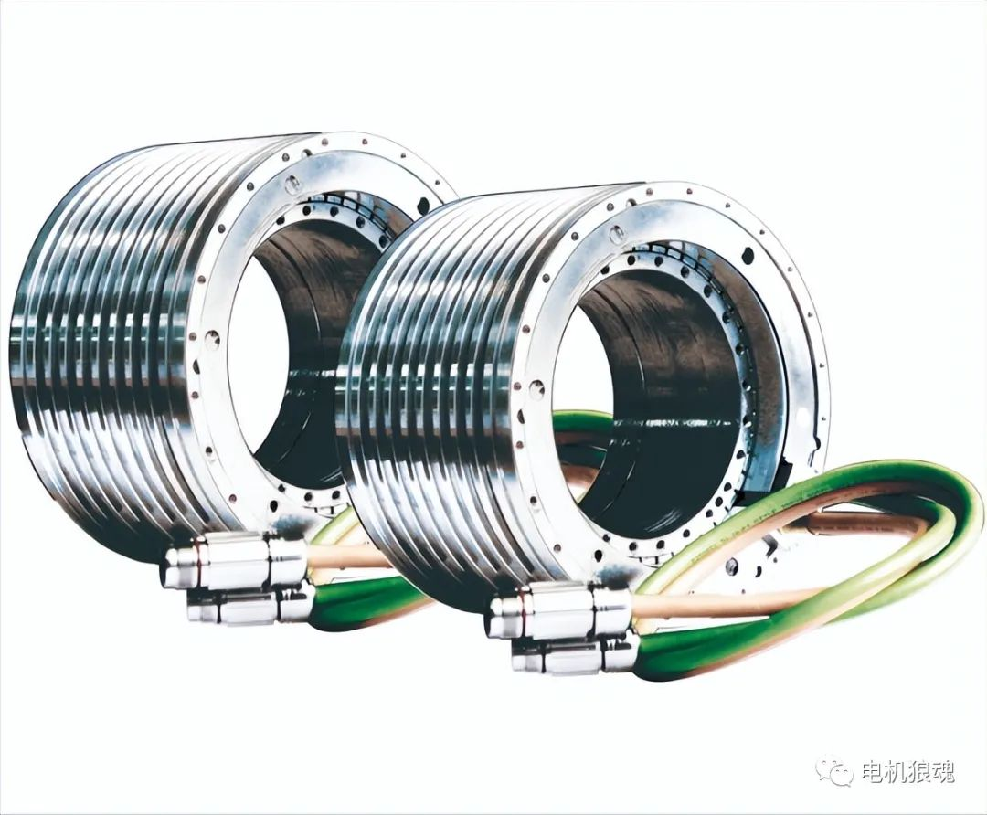
Adjust-Speed Synchronous Machines:
In a variable speed permanent magnet synchronous machine, the machine can operate as a generator or as a motor. When operating as a motor, the stator multi-phase windings can be powered by a sinusoidal AC source or by a DC source through a DC-to-AC inverter; when operating as a generator, the stator multi-phase windings provide AC power to the electrical load.
When the stator windings are fed by a DC-to-AC inverter, in which case an adjustable speed permanent magnet synchronous motor (ASSM) operates as a motor, the analysis method is similar to that of a brushless permanent magnet DC motor (BLDC). The stator multi-phase armature windings are connected to the DC power supply through a DC inverter to generate a rotating magnetic field in the air gap. The main difference between ASSM and BLDC is that in BLDC, the trigger time depends entirely on the rotor position; but in ASSM, the trigger Time is independent of rotor position. If the mechanical load of the BLDC increases, the rotor speed and induced voltage decrease, causing the armature current and torque to increase to balance the increased mechanical load. Whereas for ASSM, if the mechanical load increases, the rotor speed drops momentarily, causing the torque angle (same as the BLDC trigger lead angle) to increase, and then the torque increases to maintain the synchronous speed.
 XINDA
XINDA