


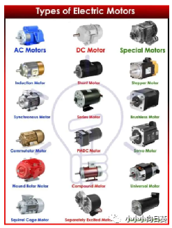
Types of Motors – Classification of AC, DC and Special Motors
An electric motor is a machine that converts electrical energy into mechanical energy. It is used to generate torque to lift loads, move objects and various other mechanical jobs. In the following article, we will discuss about different types of motors such as AC, DC and special types of motors etc.
There are three main types of electric motors.
1. AC motor
2. DC motor
3. Special motor
AC motor
AC motors convert alternating (alternating current) electrical energy into mechanical energy. These motors are powered by either single-phase or three-phase alternating current. The basic working principle of an AC motor is the rotating magnetic field (RMF) generated when alternating current passes through the stator windings. The rotor (with its own magnetic field) follows the RMF and starts spinning.
AC motors are further divided into two types.
synchronous motor
asynchronous or induction motor
synchronous motor
As the name suggests, this type of AC motor has a constant speed called synchronous speed, which depends only on the frequency of the mains current. The speed of this type of motor varies only with the supply frequency and remains constant as the load varies. It is used for constant speed applications and precision control.
A synchronous motor has the same stator design as an asynchronous motor, which produces a rotating magnetic field when supplied with an input alternating current. Although the rotor design may vary i.e. it uses a separate DC excitation to generate its own magnetic field.
Excited synchronous motor
Such synchronous motors require DC excitation. DC excitation means that the rotor has a separate DC power source to generate its own magnetic flux. This flux reacts with the rotating flux of the stator to generate rotation. A wound rotor with a commutator and brush assembly is used to supply current to the windings of the rotor.
single phase synchronous motor
This type of synchronous motor operates on a single-phase AC power supply. To be precise, it actually uses two phases, the second phase being derived from the first. The reason for using two phases is that a single phase cannot generate a rotating magnetic field. This motor can be started in either direction, i.e. its direction is indeterminate, that's why there is an additional starting arrangement for giving it a direction.
The speed of such a motor depends only on the power frequency. They are used in recording instruments, electronic wall clocks.
three-phase synchronous motor
These synchronous motors run on three-phase power. The benefit of three-phase alternating current is that it produces a rotating magnetic field in the stator, and the alignment of the phases determines the direction of rotation. These motors do not require any special actuation mechanism to determine their direction. However, the rotor still requires an additional DC power source for excitation.
They are used in industrial applications that require constant speed over a range of loads and precise positioning in robots.
non-excited synchronous motor
This kind of synchronous motor that does not require DC excitation, that is, the rotor does not need a separate DC power source to generate magnetic flux. They use a squirrel-cage rotor, such as those used in induction motors.
Hysteresis motor
This type of synchronous motor operates on the principle of hysteresis losses or residual magnetism occurring in the rotor. This type of motor operates on single-phase and three-phase AC power. In a single phase hysteresis motor, as in a reluctance motor, there is an auxiliary winding next to the main winding. Cylindrical rotors are made of ferromagnetic materials such as hardened steel with high magnetic retention or hysteresis loss. The rotor is supported by a non-magnetic shaft.
The motor starts as an induction motor. The rotating magnetic field of the stator induces eddy currents in the rotor. Due to the high hysteresis loss characteristic of the rotor material, the eddy currents together with the hysteresis torque generate torque. Due to the eddy current torque, the motor behaves as an induction motor.
Once the motor reaches a near-synchronous speed, the rotating magnetic field of the stator pulls the rotor synchronously. Due to the RMF of the stator, the ferromagnetic nature of the rotor produces opposite poles and it begins to behave as a permanent magnet. At these speeds, there is no relative motion between the stator and rotor. So no induction. Therefore, there is no eddy current or eddy torque. Due to hysteresis, the motor produces torque at synchronous speed, which is why it is named hysteresis motor.
The main advantage of a hysteresis motor is that it is brushless and has no windings inside the rotor. It doesn't make any noise and runs quietly.
reluctance motor
It is a single-phase synchronous motor that works on the basis of reluctance to generate torque. There are two types of stator windings, primary and auxiliary. Auxiliary winding for starting the motor. It has a squirrel-cage rotor (no windings), like an induction motor made of ferromagnetic material.
The motor starts like an actual single phase induction motor using the auxiliary winding. Once the motor reaches near synchronous speed, the auxiliary winding is disconnected and the rotor is locked into sync as the ferromagnetic nature of the rotor tries to hold itself within the rotating field where there is less reluctance.
Disadvantages
it produces very low torque
If the load torque increases by a certain limit, its speed drops, so it no longer operates as a synchronous motor
its less efficient
It is only available in small sizes.
It is used on turntables that require a constant speed for both record and playback functions. In addition, electronic clocks need constant speed, etc. Induction motor
AC motor types that never run at synchronous speed are called asynchronous speed. Its rotor speed is always less than the synchronous speed. It does not require separate rotor excitation.
Asynchronous motors are briefly divided into two types;
induction motor
commutator motor
induction motor
The induction motor is an AC asynchronous motor, and its working principle is the electromagnetic induction between the stator and the rotor. The rotating magnetic flux induces a current in the rotor due to electromagnetic induction, thereby generating torque in the rotor. It is the most commonly used motor in industry.
According to the structure of its rotor, it is mainly divided into two types.
Squirrel cage induction motor
The rotor of this induction motor resembles a squirrel cage. It is made of copper strips connected at both ends, using conductive rings to form a closed loop circuit. The rotor is not electrically connected.
The changing magnetic field of the stator induces a current in the bars of the rotor. The induced current creates its own magnetic field in the rotor which interacts with the rotating magnetic field of the stator and tries to cancel it by rotating in the same direction.
It is simple in design, inexpensive and more reliable. Less maintenance is required as there are no electrical connections or commutator and brush assemblies.
Slip ring or wound rotor induction motors
Slip ring or wound rotor induction motors are another type of induction motor in which the rotor consists of windings connected to slip rings . Slip rings are used to connect the windings to external resistors to control the rotor current, allowing control of the speed/torque characteristics.
It works on the same principle as a squirrel cage induction motor except that the induced current in the rotor can be controlled using an external resistor . External resistors also help increase rotor resistance during motor startup to reduce high inrush currents. It also increases the starting torque for left high inertia loads.
The disadvantage of the slip ring is that it is constantly sliding with the brushes, requiring expensive maintenance due to mechanical wear. The structure is complex and more expensive than squirrel-cage motors.
Capacitor start induction run motor
It is a single-phase induction motor that utilizes a capacitor in series with its auxiliary winding to generate additional torque during start-up. Its name clearly indicates that the capacitor is only used to start the motor, it is disconnected once the motor reaches near synchronous speed using a centrifugal switch.
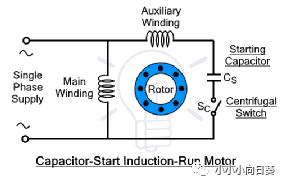
It has two stator windings called main and auxiliary. The auxiliary winding is connected in series with a capacitor using a centrifugal switch. When the motor starts, current flows through both windings, producing a high starting torque. Once the motor reaches 70-80% full speed, the centrifugal switch disconnects power to the auxiliary winding. The motor resumes running on the main winding.
Capacitor start and capacitor run motors
It is also a single phase induction motor but uses two capacitors in operation . These two capacitors are the start capacitor and the run capacitor. The start capacitor is only used for the start capacitor to provide extra high starting torque, while the run capacitor is used for normal operation to run the motor. The start capacitor is connected and disconnected using a centrifugal switch.
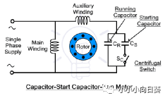
When the motor starts, both capacitors are connected to provide high starting torque to the rotor. As the speed of the rotor increases, the switch disconnects the start capacitor. This motor uses the main and auxiliary windings consecutively, which is why it runs smoother than motors that run on only the main winding, such as capacitor run motors.
commutator motor
This is an AC motor that utilizes a commutator and brush assembly to power its rotor. This motor has a wound rotor.
AC series motor
As we all know, electric motors have two types of windings, the stator windings called field windings and the rotor windings or armature windings.
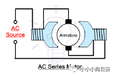
When these two windings are connected in series, it is called a series wound motor. It is also known as a universal motor because of its ability to operate on both AC and DC power.
The field winding carries the same current as the rotor winding. The brushes, which supply current to the armature winding through the commutator, short-circuit the armature winding and act as a short-circuit transformer. The arc created by the paintbrush decreases as the speed increases.
AC compensation series motor
It is a modified form of AC series motors where an additional winding called compensation winding is added in series with the existing field and armature windings to eliminate the transformer effect that occurs in uncompensated series motors.
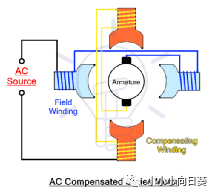
In addition to the field windings, compensation windings are added in the stator, connected as shown, to eliminate or mitigate arcing problems.
repulsion motor
A repulsion motor is also an AC single-phase motor in which the AC input is applied only to the field or stator windings. The armature winding is connected to the commutator. The armature windings are shorted by using a pair of shorting brushes. There is no electrical connection between the field winding and the armature winding. The rotor current is generated by induction.
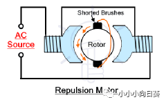
The brushes are configured in such a way that they can be moved to change their angle relative to the imaginary stator axis. The motor can be stopped, started and reversed by changing the angle of the brushes, as well as changing the speed of the motor.
When the brushes are used to short the rotor to form a loop, a current is induced as the alternating current flows in the field winding. This induced current flowing in the rotor windings creates its own magnetic field. The direction of the magnetic field depends on the angle of the brush. This magnetic field interacts with that of the stator, and the rotor reacts accordingly. For rotation, the brushes are rotated slightly by 20° in either direction to rotate the motor in that direction. Placing the brushes at 90° or 180° or 0° will stop the motor. Changing the angle increases or decreases the repulsive force between the stator and rotor fields, and the speed of the rotor varies.
The starting torque can also be controlled by varying the angle of the brushes, giving maximum starting torque at 45°. This motor was used for traction due to its excellent speed regulation, but it has been replaced by other traction motors.
Repulsion start induction run motor
Repulsion induction motors or also known as repulsion start induction run motors are a modified version of squirrel cage induction motors that use the high starting torque characteristics of repulsion motors and typically operate as squirrel cage induction motors.
There is a special mechanism to start and run the motor. During motor starting, a pair of shorting brushes is connected at an angle to the commutator, as in a repulsion motor. Once the motor picks up speed, the mechanism lifts the brushes and connects the rods together by shorting the commutator, creating a squirrel-cage rotor. The motor resumes operation as an induction motor.
The advantage of repulsion start provides 5-6 times higher starting torque compared to any other induction motor. The brush also lasts longer since it is only used to start the motor. Therefore, these motors have a high mechanical life and require less maintenance.
DC motor
DC motors are the other main type of electric motor and operate on direct current or direct current only. There are no phases in DC, that's why DC motors run using only 2 wires. They were the first electric motors to be invented. Its speed can be more easily controlled by simply changing the supply voltage. It provides simple start, stop, acceleration and reverse mechanisms. DC motors are very cheap to install, but they do require maintenance, the cost of which increases significantly with the size and power of the motor.
The basic working principle of DC motor is Fleming's left hand rule. Current-carrying conductors within a magnetic field experience thrust forces perpendicular to each other.
DC motors can be briefly divided into the following types
Brushed DC Motor
Brushless DC Motor
Coreless or Ironless DC Motors
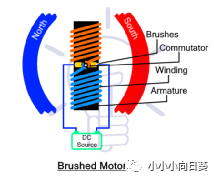
Brushed DC Motor
As the name suggests, this type of DC motor has brushes and a commutator. They are used to connect fixed circuits with rotating circuits. In this case, the rotor windings of the motor are energized through conductive brushes. The downside of any brushed motor is that they require frequent maintenance due to the constant sliding of the brushes and the sparking between them. However, they are very simple in design and expensive.
Brushed DC motors are further divided into
Shunt motor
self-excited dc motor
Permanent Magnet DC Motor
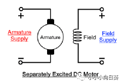
Shunt Excited DC Motor
This type of DC motor has a separate field. Excitation refers to the energization of the field winding, also known as the stator winding. Both windings, the field winding and the winding of the armature, are connected to a separate power supply.
self-excited dc motor
This type of brushed DC motor has a self-exciting field winding. The field winding is electrically connected to the armature winding. A single power supply powers both windings. Therefore, it does not require a separate excitation source.
However, the field winding can be configured in series, parallel and partly in series with the armature winding. That is why self-excited DC motors are further divided into the following types.
Series winding
shunt wound
Composite winding
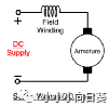
Series Wound DC Motor
In a series wound DC motor, the field winding is connected in series with the armature winding. Therefore, the current flowing through the field winding is the same as the current flowing through the armature winding.

The speed of this motor varies with the load connected to the motor.
Parallel Wound DC Motors
This type of DC motor has a field winding (also known as a shunt field winding) connected in parallel with the armature winding. It allows full terminal voltage across the field winding with the same amount of voltage across both windings. The supplied current is divided into excitation current and armature current.
This type of motor is used for its constant speed applications as it maintains its speed over the range of loads it is connected to. Parallel windings are windings connected in parallel.
Composite Wound DC Motor
Compound-wound DC motors take advantage of the characteristics of series-wound and parallel-wound DC motors. It combines parallel and series combinations of field and armature windings.
Due to the combination of series and parallel windings, composite winding motors can be classified into the following two types according to the nature of the windings.
cumulative compound
differential composite
cumulative compound
When the parallel field and series field windings generate flux in the same direction, the flux of the parallel field contributes to the increase of the main series field flux, and the motor is called a cumulative compound wound motor.
The resulting total flux in this case is always greater than the original flux.
differential composite
When parallel excitation and series excitation windings generate magnetic flux in opposite directions, the effect of mutual reduction of magnetic flux is called differential compound DC motor.
The total flux they generate is always less than the original flux. They cannot find any practical application in the industry.
Both compound motors can be short-shunt and long-shunt, depending on the winding arrangement. Short parallel and long parallel DC motors are explained below.
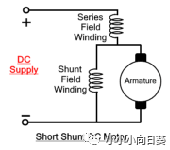
Short Parallel DC Motors
If the parallel field winding is only parallel to the armature winding and in series with the field winding as shown in the diagram below, the motor is called a short parallel DC motor. It is also known as compound wound motor.
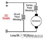
Long Parallel DC Motor
If the parallel field winding is connected in parallel with the armature winding and the field winding, the DC motor is called a long parallel motor.
Permanent Magnet DC Motor
Permanent magnet DC motors or simply PMDC motors are another type of brushed DC motor. It has the usual armature, like the other brushed DC motors explained above. However, there is no stator or field windings and the magnetic field is generated using permanent magnets placed in the stator.
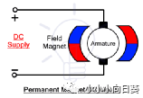
When the armature winding carrying the input current is placed inside the N & S poles of the magnet. A magnetic field interacts with it, and the armature experiences a rotational force.
Permanent magnets produce a fixed magnetic field that is designed at the time of construction and cannot be changed afterwards. However, the strength of a magnet will decrease over time. An additional excitation field is found in some designs, which helps increase its magnetic strength when it is reduced.
PMDC does not require excitation to generate field flux as it is produced by permanent magnets. This increases its efficiency, since the excitation does not consume additional power. The absence of a field winding greatly reduces the overall motor size. Therefore, PMDC motors have a compact design. They are also very cheap and best suited for low power applications.
Brushless DC Motor
As the name suggests, brushless or BLDC motors are the other main type of DC motor without any carbon brushes and commutator components. This means that the input power is not supplied to the rotating part of the motor, but to the stator of the motor, which in this case consists of multiple windings and the rotor is made of permanent magnets.
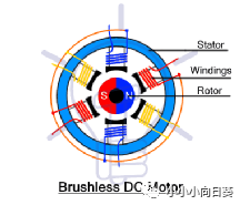
It has multiple stator windings, each placed at a different angle to create flux in a different direction. The input is switched between the stator's windings to create a magnetic field that pushes and pulls the rotor's field, causing it to spin in its direction. Hall effect sensors are used to detect the position of the rotor and switch the input to the correct stator winding respectively.
Since the DC input to the stator needs to be switched, this motor uses electronic commutation rather than mechanical commutation using switching devices such as thyristors. These switches are controlled using a microcontroller to precisely switch the input between the stator windings. It basically switches the DC input to a three-phase power supply, which creates a smooth rotating magnetic field.
Brushless motor speed depends on the frequency of the AC power supplied by the controller. That's why it is also called synchronous motor
Controllers for brushless motors are more complex and very expensive. It cannot operate without a controller, which also provides precise speed control and positioning of the rotor. But the cost of the controller is far greater than the motor itself.
Since there are no brushes, there is no electrical or electromagnetic noise and sparks from mechanical commutation. It helps to extend the life of the motor as well as the efficiency of the motor. The energy dissipated in the brushes is converted into a mechanical output. And they are also maintenance-free.
Coreless or Ironless DC Motors
As the name suggests, this type of DC motor does not have a laminated iron core. The rotor windings are wound in a canted or honeycomb pattern, forming a self-supporting hollow cage, usually made using epoxy resin. A rotor made of permanent magnets is arranged in the hollow rotor.
The coreless design eliminates the problems and losses associated with traditional motor cores. For example, this motor has no iron loss, which can increase the efficiency of the motor to 90%. The design also reduces winding inductance, which reduces sparking between the brushes and the commutator, extending the life of the motor. It also reduces the mass and inertia of the rotor, which also increases the acceleration and deceleration rate of the motor.
Special motor
There are several types of specialty motors that are modified versions of other motors designed for special purposes. Some of these motors are given below.
servo motor
A servo motor is a special type of motor used to push/pull or lift or rotate an object at a certain angle. Servo motors can be designed to operate on both AC and DC power sources. A servo motor that runs on DC power is called a DC servo motor, while a servo motor that runs on AC power is called an AC servo motor. It's a simple motor with a controller and multiple gears to increase its torque.
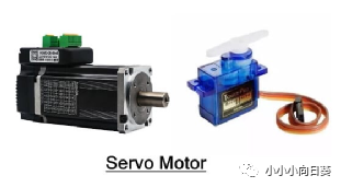
These motors are rated in kilograms per centimeter (kg/cm). It specifies how much weight the servo can lift over a specific distance. For example, a servo rated at 3 kg/cm can lift a 1 kg load 3 cm from its axis. Lifting capacity decreases with distance.
Servo motors have gear assemblies, controllers, sensors, and feedback systems. Gear assemblies are used to reduce the speed and increase its torque significantly. The controller is used to compare the input signal (desired position) with the sensor signal (actual position of the servo) obtained through the feedback system. The controller compares the two signals and removes the error between them by rotating the motor shaft.
A servo motor has three wires. Two of them are used to provide power while the third is used to control the position of the servo. It is controlled by providing a pulsating signal through a microcontroller using PWM (Pulse Width Modulation).
The servo can be turned 90° in either direction, making it a total of 180°. Neutrally, it is in the middle of 90°. It can be rotated by varying the pulse width between 1ms and 2ms, where 1ms corresponds to 0°, 1.5ms to 90° and 2ms to a 180° angle of the axis.
direct drive
Direct drive motors or also known as torque motors are another type of motor that can produce high torque at low speeds even when stalled. The payload is directly connected to the rotor, so there is no need for gearboxes, belts, reducers, etc. It is a brushless permanent magnet synchronous motor without commutator and brushes. Reliable and long service life due to no mechanical wear. The fact that it has fewer mechanical parts means it requires less maintenance and is low cost.
Linear Motor
Linear motors have an unfolded stator and rotor that provide linear rather than rotational force. If you cut open any motor and lay it flat on a surface, you'd get a linear motor.
The armature windings are designed in a linear fashion and carry 3-phase currents to generate a magnetic field. The magnetic field does not rotate, but moves in a straight line. The magnetic field interacts with the field generated by a flat permanent magnet located beneath it. The interaction between them creates a linear force on each other, so the armature moves forward or backward.
It is an AC powered motor with a controller, such as a servo motor. Power is supplied to the main part of the motor containing the windings. It generates its own magnetic field, the polarity of which depends on the phase of the AC power supply. The secondary part of the motor is a permanent magnet whose magnetic field interacts with that of the primary part, as a result attracting and repelling it by creating a linear force. The amount of current determines the force, and the rate of change of current determines the speed of the primary.
Linear motors are used in robotics, medical equipment, and factory automation, among others.
stepper motor
A stepper motor or stepper motor is a brushless DC motor whose full rotation is divided into a number of equal steps . This type of motor rotates in steps (a fixed number of degrees), rather than continuously. This stepping motion provides high precision and is used in robotics.
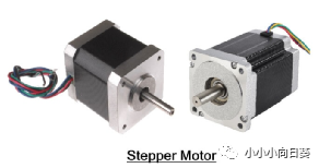
Stepper motors work with pulses. Each pulse moves the motor one step. The accuracy of the motor depends on the number of steps per revolution. The step size is determined during its design. However, the speed of the motor can be controlled by applying a variable frequency pulse train. The controller inside the servo moves the rotor one step forward or backward with each pulse.
It is used for its accurate and precise positioning. It delivers full torque from a standstill. It has low maintenance requirements due to its brushless design. Therefore, they are very reliable and have a long service life.
Stepper motors are used in industrial machines due to their precise positioning, for the automatic manufacture of products, CNC based machines. It also finds applications in medical devices and machinery, as well as security cameras. Steppers are widely used in electronics and other intelligent electronic systems.
General motor
A universal motor is a special type of motor that can run on both AC and DC power. It is a brushed series wound motor in which the field winding is connected in series with the armature winding. They provide maximum starting torque at high operating speeds.
Since the windings are connected in series, the direction of the current flow through the two windings remains the same even if the direction of the current is reversed many times in a second. Although, the motor may run slower on AC due to the reactance of the windings.
 XINDA
XINDA