


Briefly analyze the number of DC motor commutators and relative position control
The winding of the DC motor rotates in the DC magnetic field to induce an AC potential, and then the AC potential is converted into a DC potential through the commutation device. When the DC motor is working, if the induced potential is overcome under the action of the external DC voltage to make the current flow through the winding, then the electromagnetic power is input, which is converted into mechanical power on the output shaft of the motor after offsetting various losses, and drives the equipment to run; if the induced potential is overcome Winding voltage drop to output DC current requires power equipment to drive the motor shaft to rotate, offset various losses and then convert it into electric power for output to the external circuit. At this time, the electromagnetic power includes the resistance loss of the armature winding and the electric power output to the external circuit.
The magnetic pole of the DC motor is fixed, the DC current flows through the magnetic pole coil to generate a DC magnetic field, and the armature winding and the commutation device rotate synchronously. Since the stationary brush and the reversing device are always in sliding contact with the magnetic pole, the seamless connection between the external line DC and the internal AC of the winding is realized.
The commutator consists of many commutator segments, which are insulated from each other by mica material and are also insulated from the ground.
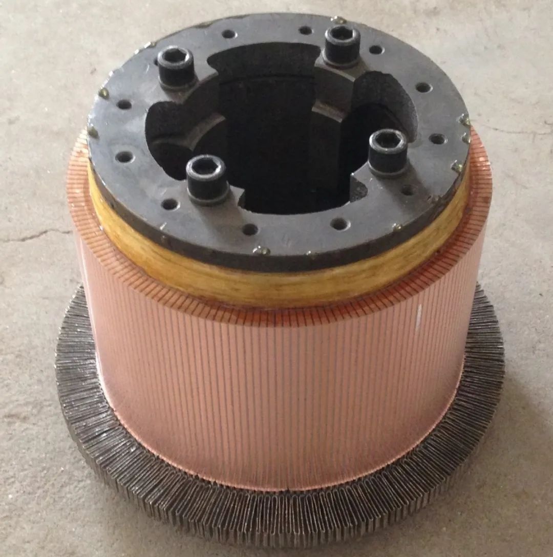
The armature winding of the DC motor is composed of coil elements with insulated wires, which are embedded in the armature core slot of the ground motor. These coils are connected to the commutator segments according to certain rules. The coil element may be single-turn or multi-turn. Generally, small-capacity motors have a multi-turn structure, while large-scale motors have a single-turn structure. The number of commutator segments is directly related to the number of slots in the motor.
When there is only one element side per slot and each layer, the number of commutation pieces is equal to the number of slots. Only when the center of the insulating piece is aligned with the center of the iron core slot or tooth, can the terminal symmetrical winding be realized. At this time, the brush only needs to be placed on the main On the commutator piece under the pole axis, the maximum potential can be obtained, and the potential of the component short-circuited by the brush is equal to zero or close to zero. When there is more than one component side per slot and layer, it is impossible to align the center of each insulating sheet with the iron core slot, but the center line of the integer pair of commutator segments should be aligned with the iron core slot or tooth center line. If it is not press-fitted according to the above rules, the position of the brush should be moved through the same angle accordingly.
In the actual application process, we found that some DC motors have an odd number of commutator segments, and some have an even number, which is directly related to the number of motor slots and winding types, such as the number of armature slots of a single-wave winding motor, the number of winding elements The number of pieces and the number of commutation pieces cannot be even, but must be odd, otherwise the armature cannot be connected into a closed loop after embedding wires. Permanent magnet DC motors generally use single-wave windings in order to increase the armature resistance, so their number of commutation pieces is odd rather than even.
 XINDA
XINDA