


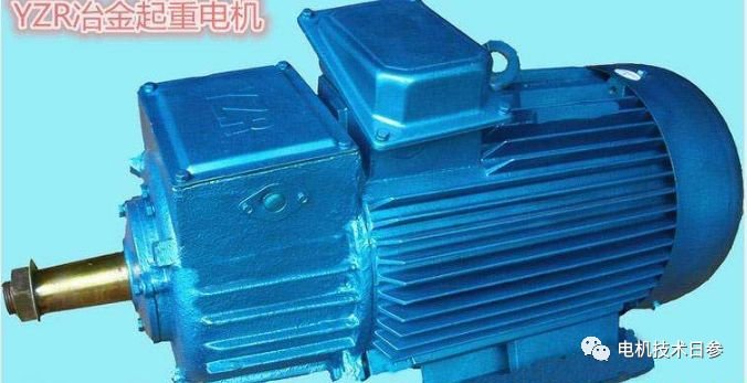
Test Features of Three-phase Asynchronous Motor with Wound Rotor
The main feature of the wound rotor three-phase asynchronous motor is that its rotor winding can be connected in series with an external resistor, and the total resistance of the rotor winding circuit can be changed by changing the resistance value of the external resistor, thereby changing its starting current and starting torque. The larger the external resistance, the smaller the starting current and the larger the starting torque. It can be seen from its characteristics that this type of motor is mainly used in occasions where the power supply capacity is small and high starting torque is required; because the external resistance of the rotor can be adjusted to adjust the speed within a certain range, it is also used in some equipment that requires a small amount of speed adjustment. .
●Measurement test of stator and rotor voltage ratio
The stator-rotor voltage ratio is an assessment index given in the technical conditions of wound-rotor three-phase asynchronous motors. The test for measuring the stator-rotor voltage ratio of a wound rotor three-phase asynchronous motor is also called the test for measuring the rotor open circuit voltage.
(1) Test method. Before the test is energized, in order to prevent the rotor from rotating due to the torque generated by the induced current in the rotor core when the power is energized, the rotor should be blocked with an instrument in advance. Before blocking the rotor, turn on the power to observe the direction of rotation of the rotor, and then install the blocking device. For a motor with a smaller capacity, a high-strength wooden board can be used to support the keyway of the motor shaft extension.
During the test, the three-phase winding of the rotor is open circuited. Add the rated voltage U 1N of the rated frequency to the stator winding . Measure the induced electromotive force generated by the three windings between every two collector rings (used to be called rotor line voltage U 21 , U 22 , U 23 ). When measuring, use a voltmeter and test leads with insulation that meets the requirements, and pay attention to prevent electric shock .
(2) Calculation and processing of test results
Calculate the unbalance of the three line voltages of the measured rotor. When the three-phase voltage of the stator is balanced, this value should not exceed ±5%. Calculate the voltage ratio K U by comparing the average value U2 of the three line voltages of the rotor with the rated voltage U1N of the stator , see formula (1) for details.
K U =U 1N /U 2 ………………(1)
The voltage ratio is generally not a percentage or a simplified fraction, but is directly given as a fraction of the stator rated voltage. When there is a difference between the measured value of the stator voltage and the rated value during the test, it should be corrected to the value at the rated value according to the proportional relationship.
●Determination of DC resistance of rotor winding
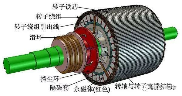
The three-phase rotor windings of the three-phase wound rotor asynchronous motor are generally connected in a star shape, and the inside of the motor has been sealed, and the neutral wire is not drawn out. So only three wire resistances can be measured outside the motor. Unless otherwise specified, the measurement shall be carried out between the three slip rings.
●Determination of rotor winding temperature rise
Test methods and related calculations for thermal tests with stator windings. It should be noted that during the process of measuring the thermal DC resistance during the temperature rise and stable shutdown, the two resistance measuring instruments connected to the stator and rotor windings cannot repeatedly switch on and off their respective power supplies, otherwise it will be affected by the induced electromotive force generated by the windings. Measurement.
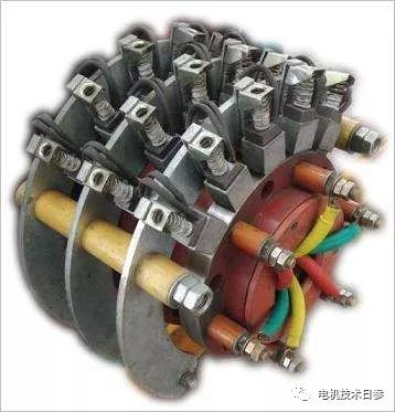
●Check the pressure on the brush and the contact with the collector ring
( 1 ) The hook-pull brush can use the brush braid (two brush braids and symmetrical) or a wire passed through after punching a horizontal hole at the upper end, and press a thin and smooth paper between the brush and the brush in advance. between the collector rings. Use a small spring balance hook to pull the upper end of the brush, pull the spring balance along the radial direction of the collector ring (perpendicular to the working surface of the collector ring), and at the same time gently pull the paper outward. When the paper can be pulled out, it is the moment when the brush has just left the surface of the collector ring. At this time, the indication value of the spring balance is the pressure on the brush.
(2) How to judge whether the brush pressure is normal
Find the pressure exerted by the brushes on the surface of the slip ring. Divide the measured brush pressure by the actual contact area between the brush and the collector ring to obtain the pressure applied by the brush to the collector ring.
(3) Check the contact area between the brush and the slip ring
The inspection of the contact area between the brush and the slip ring can be roughly obtained by visual inspection. If a more accurate value is required, a layer of red red powder or red (blue) ink or white chalk is applied on the working surface of the brush in advance. Wait, put the brush into the brush box, adjust the pressure, turn the rotor of the motor for several circles, take off the brush, and watch the area of the coating that has been wiped off. The percentage of this area to the total area of the brush working surface is percentage of contact area.
● Perform locked-rotor test under low voltage
The locked-rotor test under low voltage is an inspection test item, and its purpose is the same as that of ordinary cage rotor motors. The applied voltage and the data to be measured are the same as those related to the locked-rotor test in the inspection test of ordinary cage rotor motors. During the test, the rotor should be blocked. If there is no brush lifting device, the rotor winding should be short-circuited on the collector ring or its three-phase lead wires should be connected together for short circuit; if there is a brush lifting device, place the brush lifting device in the "running "Location.
 XINDA
XINDA