![]() The speed formula of the three-phase asynchronous motor is: n=60f/p(1-s)
The speed formula of the three-phase asynchronous motor is: n=60f/p(1-s)
It can be seen from the above formula that the purpose of changing the speed can be achieved by changing the power supply frequency f, the number of pole pairs p of the motor and the slip rate s. From the point of view of the essence of speed regulation, different speed regulation methods are nothing more than changing the synchronous speed of the AC motor or not changing the synchronous rotation .
The speed regulation methods that do not change the synchronous speed are widely used in production machinery, such as rotor series resistance speed regulation of winding motors, chopper speed regulation, cascade speed regulation, and the application of electromagnetic slip clutches, hydraulic couplings, oil film clutches, etc. speed regulation. There are multi-speed motors that change the number of stator pole pairs to change the synchronous speed, variable frequency speed regulation that changes the stator voltage and frequency, and motor speed regulation without commutation.From the point of view of energy consumption during speed regulation, there are two methods of high-efficiency speed regulation and low-efficiency speed regulation: high-efficiency speed regulation means that the slip rate remains unchanged, so there is no slip loss, such as multi-speed motors, frequency conversion speed regulation and The speed regulation method that can recover the slip loss (such as cascade speed regulation, etc.). The speed regulation method with slip loss is an inefficient speed regulation method, such as the rotor series resistance speed regulation method, the energy is lost in the rotor circuit; the electromagnetic clutch speed regulation method, the energy loss is in the clutch coil; the hydraulic coupling speed regulation method , the energy loss is in the oil of the fluid coupling. Generally speaking, the slip loss increases with the expansion of the speed regulation range. If the speed regulation range is not large, the energy loss is very small.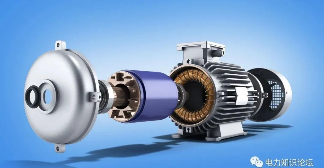
1. Variable pole logarithmic speed regulation method:This method of speed regulation is to change the wiring method of the stator winding to change the number of pole pairs of the motor stator to achieve the purpose of speed regulation. The characteristics are as follows: It has relatively hard mechanical characteristics and good stability; no slip loss and high efficiency; Easy to control and low price; there are steps for speed regulation, and the step difference is large, so smooth speed regulation cannot be obtained; it can be used in conjunction with voltage regulation speed regulation and electromagnetic slip clutch to obtain smooth speed regulation characteristics with high efficiency.This method is suitable for production machinery that does not require stepless speed regulation, such as metal cutting machine tools, elevators, lifting equipment, fans, water pumps, etc.Second, frequency conversion speed regulation method:
Frequency conversion speed regulation is a speed regulation method that changes the frequency of the motor stator power supply, thereby changing its synchronous speed. The main equipment of frequency conversion speed regulation system is the frequency converter that provides variable frequency power supply. The frequency converter can be divided into AC-DC-AC frequency converter and AC-AC frequency converter. At present, AC-DC-AC frequency converter is mostly used in China. Its characteristics: high efficiency, no additional loss in the speed regulation process; wide application range, can be used for cage-type asynchronous motors; large speed regulation range, hard characteristics, high precision; complex technology, high cost, difficult maintenance and repair. This method is suitable for occasions requiring high precision and good speed regulation performance. 3. Cascade speed regulation method:
Cascade speed regulation means that an adjustable additional potential is connected in series in the rotor circuit of a wound motor to change the slip of the motor and achieve the purpose of speed regulation. Most of the slip power is absorbed by the additional potential connected in series, and then used to generate additional devices to return the absorbed slip power to the grid or convert energy for use. According to the way of slip power absorption and utilization, cascade speed regulation can be divided into motor cascade speed regulation, mechanical cascade speed regulation and thyristor cascade speed regulation. Thyristor cascade speed regulation is mostly used, and its characteristics are:The slip loss during the speed regulation process can be fed back to the power grid or production machinery, with high efficiency; the device capacity is proportional to the speed regulation range, saving investment, and is suitable for production machinery with a speed regulation range of 70%-90% of the rated speed Above; when the speed control device fails, it can be switched to full-speed operation to avoid production stoppage; the power factor of the thyristor cascade speed control is low, and the harmonic influence is relatively large. The method is suitable for use on fans, water pumps, steel rolling mills, mine hoists and extrusion machines. 4. Speed regulation method of winding motor rotor series resistance:
The rotor of the wound asynchronous motor is connected in series with an additional resistor, which increases the slip rate of the motor, and the motor runs at a lower speed. The larger the resistance connected in series, the lower the speed of the motor. This method has simple equipment and convenient control, but the slip power is consumed on the resistor in the form of heat. It belongs to stepped speed regulation, and its mechanical characteristics are relatively soft.5. Stator voltage regulation and speed regulation method:When the stator voltage of the motor is changed, a set of different mechanical characteristic curves can be obtained, thereby obtaining different rotational speeds. Because the torque of the motor is proportional to the square of the voltage, the maximum torque drops a lot, and its speed range is small, which makes it difficult for general cage motors to be used. In order to expand the range of speed regulation, a cage motor with a large rotor resistance value should be used for voltage regulation and speed regulation, such as a torque motor specially used for voltage regulation and speed regulation, or a frequency-sensitive resistor connected in series with a wound motor. In order to expand the stable operation range, when the speed regulation is above 2: 1, the feedback control should be adopted to achieve the purpose of automatic speed regulation.
The main device for voltage regulation and speed regulation is a power supply that can provide voltage changes. At present, the commonly used voltage regulation methods include series saturated reactor, autotransformer and thyristor voltage regulation. Thyristor voltage regulation method is the best. Features of pressure regulation and speed regulation:The voltage regulation and speed regulation circuit is simple and easy to realize automatic control; during the voltage regulation process, the slip power is consumed in the rotor resistance in the form of heat, and the efficiency is low. Pressure regulation and speed regulation are generally suitable for production machinery below 100KW.6. The speed regulation method of the electromagnetic speed regulating motor:Electromagnetic variable speed motor consists of three parts: cage motor, electromagnetic slip clutch and DC excitation power supply (controller). The power of the DC excitation power supply is small, and it is usually composed of a single-phase half-wave or full-wave thyristor rectifier. Changing the conduction angle of the thyristor can change the magnitude of the excitation current. Electromagnetic slip clutch consists of three parts: armature, magnetic pole and field winding. The armature and the latter have no mechanical connection and both rotate freely.The coaxial connection between the armature and the motor rotor is called the active part, which is driven by the motor; the magnetic pole is connected with the load shaft by a coupling and is called the driven part. When both the armature and the magnetic poles are stationary, if the excitation winding is supplied with direct current, several pairs of magnetic poles with alternating N and S polarities will be formed along the circumferential surface of the air gap, and the magnetic flux will pass through the armature. When the armature rotates with the drag motor, due to the relative movement between the armature and the magnetic poles, the armature induces eddy currents, which interact with the magnetic flux to generate torque, which drives the rotor with magnetic poles to rotate in the same direction, but its The rotation speed is always lower than the rotation speed N1 of the armature, which is a slip speed regulation method, and the output torque and rotation speed of the clutch can be changed by changing the DC excitation current of the slip clutch.The speed regulation characteristics of the electromagnetic speed regulating motor: the structure of the device and the control circuit are simple, the operation is reliable, and the maintenance is convenient; the speed regulation is smooth and stepless; there is no harmonic influence on the power grid; the speed loss is large and the efficiency is low. This method is suitable for production machinery with medium and small power, which requires smooth sliding and short-term low-speed operation.7. Speed regulation method of hydraulic coupler:The hydraulic coupling is a hydraulic transmission device, generally composed of a pump wheel and a turbine, which are collectively called working wheels and placed in a sealed housing. The shell is filled with a certain amount of working liquid. When the pump wheel is driven by the prime mover to rotate, the liquid in it is driven by the blades and rotates . The turbine blades use thrust to drive the production machinery to run.The power transfer capability of the hydraulic coupling is consistent with the relative liquid filling volume in the shell. During the working process, the turbine speed of the coupler can be changed by changing the liquid filling rate to achieve stepless speed regulation. Its characteristics are: the power adaptability range is large, and it can meet the needs of different power from tens of kilowatts to thousands of kilowatts; the structure It is simple, reliable in operation, convenient in use and maintenance, and low in cost; small in size and large in capacity; convenient in control and adjustment, and easy to realize automatic control. This method is applicable to the speed regulation of fans and water pumps. The above are several common motor speed regulation methods. The first two are more common to be used in conjunction with protection. The first is variable pole number speed regulation. The more common one is a two-speed motor. Running, switching to high-speed running after changing the number of poles, this process requires a switching of the wiring mode.The second is frequency conversion speed regulation. This speed regulation method is mainly to change the frequency through the frequency converter to achieve the purpose of speed regulation. These two speed regulation methods can be used in close cooperation with MPU300.


 XINDA
XINDA