![]()
"Should I buy brushed or brushless power tools?"
"This brand of motor has more power and is cheaper, is it worth buying? "
"Why is the single-phase induction motor more expensive than the three-phase induction motor with the same power?"
As a tool lover, I often repair the electric tools at hand for relatives and friends, and I am often asked the above questions. Motor, as the core of electric tools, is something that everyone is very concerned about.
In order to let everyone really understand the principles and characteristics of the motors commonly used in power tools, I plan to write a simple article to help you choose the power tools that suit you, or perform simple repairs when the power tools fail .
Next, as a tool repairer, I will combine the characteristics of various types of motors in electric tools, and explain the principles of motors through three points:
1. Why does the motor turn?
2. How does the motor commutate?
Third, how the motor speed is adjusted.
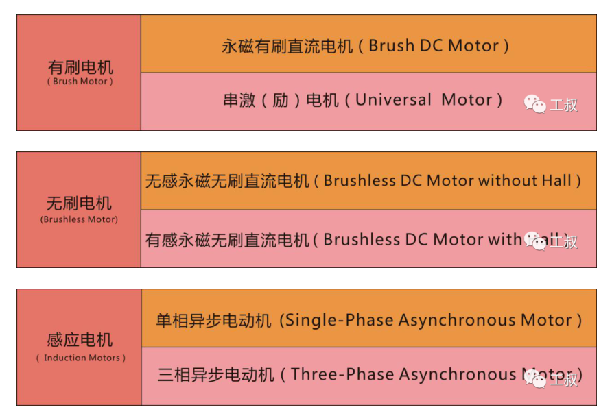
Common Motor ClassificationBefore explaining the principle, we first classify the motors commonly used in power tools.
The following three pictures simply and clearly list the corresponding types of brushed, brushless and induction motors that we often say.
Let's start with brushed motors.
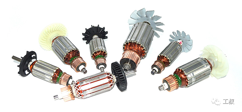
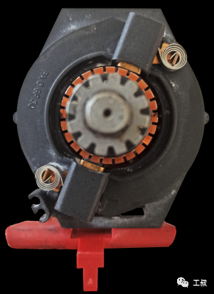
Rotor of a brushed motor
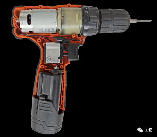
Among power tools, brushed motors are currently the most widely used category. They can be seen from small-power hand drills and electric grinders to high-power cutting machines and electric chain saws.Among them, permanent magnet brushed DC motors are often used in portable rechargeable electric tools; while series motors are mostly used in plug-in electric tools.Hand Drill Using Permanent Magnet Brushed DC Motor Electric hand drill using series motorThe permanent magnet brushed DC motor has simple structure, low manufacturing cost, stable and reliable performance, and relatively simple commutation and speed regulation circuits.So, let's look at the first question first.
Q1 Why does the permanent magnet brushed DC motor turn?The picture comes from the InternetThe above figure shows the simplest form of a permanent magnet brushed DC motor - the three-level armature windings of A, B, and C are arranged in a 120-degree ring, and two tile-shaped magnetic steels are arranged on the periphery.The current flows through the brushes into contact with the commutator (commutator), which introduces current into the armature windings.When the power is turned on, the armature winding will generate a magnetic field like an electromagnet, and at the same time interact with the surrounding tile-shaped magnets. According to the principle that the same sex repels each other and the opposite sex attracts each other, the armature will rotate around the central axis.In one rotation cycle, the armature winding of each pole will alternately generate an attraction and repulsion effect with the surrounding magnetic steel to complete a 120-degree rotation. At the same time, with the help of the commutator, it goes round and round to form continuous rotation.01 Commutation of permanent magnet brushed DC motorThere are two ways to commutate the permanent magnet brushed DC motor:First, change the polarity of the outer magnet (stator).Second, change the direction of the input current.Since the magnetic steel is a permanent magnet and placed in the form of a stator, the commutation of the permanent magnet brushed DC motor is basically achieved by changing the direction of the current.

Commutation diagram
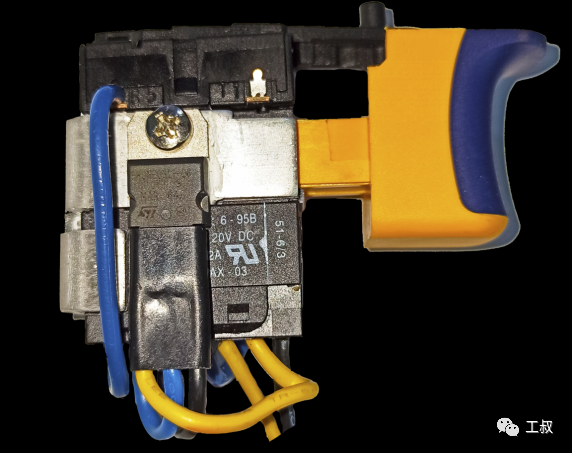
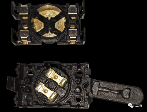
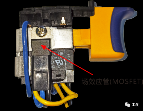
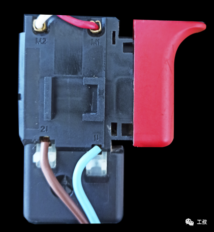
A DC speed regulating switch assembly
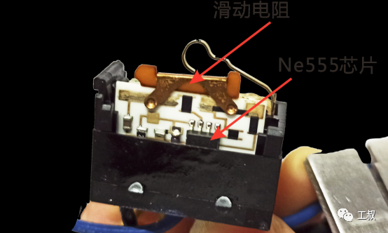
A commutator internal structure02 Speed regulation of permanent magnet brushed DC motorIn electric tools, the speed regulation of permanent magnet brushed DC motors basically adopts PWM (pulse width modulation). Use MOSFETs (Field Effect Transistors) as power devices.
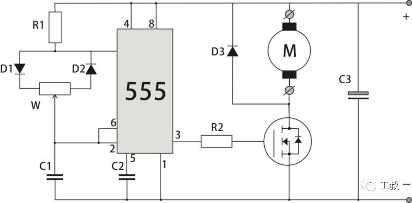
PWM DC speed regulation circuit
The circuit composed of 555 chips in the figure is used to generate PWM (pulse width modulation) signal, and then drive MOSFET field effect tube to control the power of the motor.
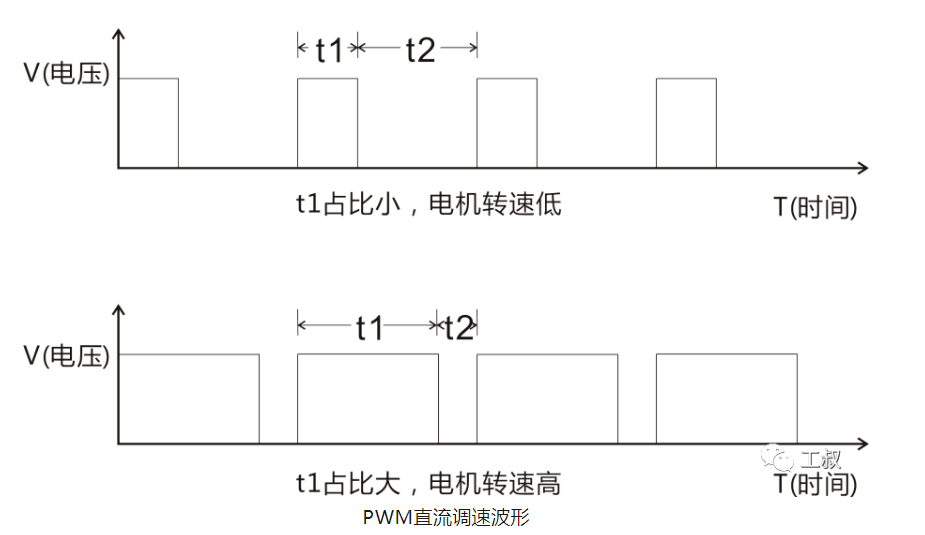
PWM DC speed regulation waveform
PWM (Pulse Width Modulation) DC motor speed regulation, in simple terms, is to control the length of time that the motor is powered on and off.In a cycle, the shorter the time the motor is powered on and the longer it is powered off, the slower the motor speed; conversely, the longer the time the motor is powered on and the shorter the time it is powered off, the faster the speed of the motor.Q2 Why does the series motor rotate?The series motor is similar to the permanent magnet DC brushed motor, the difference is that the stator is changed from a permanent magnet to an electromagnet.
The stator of the series-excited motor also contains coils, and the coils are connected in series with the brushes, so it is called a series-excited (excited) motor.
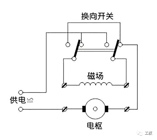
The picture comes from the Internet01 commutation of series motorThe stator and rotor coils of series motors are connected in series. When changing the polarity of the external power supply, the polarity of the stator and rotor will change at the same time. Therefore, even if the polarity of the power supply is changed, the series motor will not commutate.It is precisely because of this feature that the series motor can work normally when it is connected to a DC or AC power supply (I think that the series motor is called a universal motor abroad, which is also the reason).Series motor commutation circuitBosch TBM1000 hand drill commutatorSo, how to realize the commutation of the series motor?In fact, the method is also very simple. Since the stator coil and the rotor coil are connected in series, we can change the running direction of the series excited motor only by changing the series connection of the stator coil and the rotor coil.There is a reversing switch on our commonly used electric drills. For electric drills using series motors (generally plugged in), when we toggle the reversing switch, the serial connection between the stator and the rotor is changed. The series motor will run in the opposite direction.02 Speed regulation of series motorAlthough the commutation method of the permanent magnet DC brush motor cannot be used on the series motor, its speed regulation method is effective on the series motor.However, because most of the series motors use 220V AC, there is a simpler and more reliable way for the series motors - the AC chopping speed regulation method. The power device used is a thyristor.
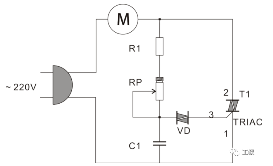
Common Speed Regulating Circuit for Series Excited Motor
A series motor speed control switch assemblyThe governor of the series motor is similar in structure to that of the DC motor, except that the circuit is simpler because the power device is replaced by a thyristor.In the figure, T1 is a bidirectional thyristor, VD is a bidirectional trigger diode, and RP is a sliding resistor with a switch (corresponding to the push switch on the power tool).
When the circuit is powered on, the voltage across C1 cannot change suddenly, and the current charges C1 through R1 and RP. When the trigger voltage of VD is reached, VD is turned on, and T1 is turned on. At this time, a current flows through the motor M. When VD is turned on, C1 discharges with the alternating current cycle. When the voltage across C1 is lower than the trigger voltage of VD, VD is disconnected, and T1 ends at the zero-crossing point of alternating current. In the process of switching on and off, it is equivalent to cutting off the current.Adjusting the potentiometer RP can change the charging speed of the capacitor C1, thus changing the on and off time of T1. In a cycle, the longer the on time, the faster the motor speed, otherwise, the lower the motor speed.Therefore, when the speed of the motor is very low, we can even hear the sound of "da da da" from the motor because the thyristor is on for a short time.








 XINDA
XINDA