


Research on key technologies of ultra-high power density motor drive system for electric vehicles
The driving force for developing an ultra-high power density motor drive system is: under the same volume or mass, the output power is greater, the overtaking acceleration ability and high-speed continuous driving ability are stronger, and excellent power performance and driving experience are obtained; under the same output power, the small Lightweight design, high performance in a given space, flexible layout, better vehicle loading, conducive to platform modularization and four-wheel drive layout, suitable for original electric chassis architecture design, less material consumption, and lower cost.
1 Theoretical analysis
The industry has not yet unified the definition of power density. We have clarified the calculation method for different index definitions and analyzed the index connotation, as shown in Table 1.
Table 1 Definition and connotation of power density index of motor drive system
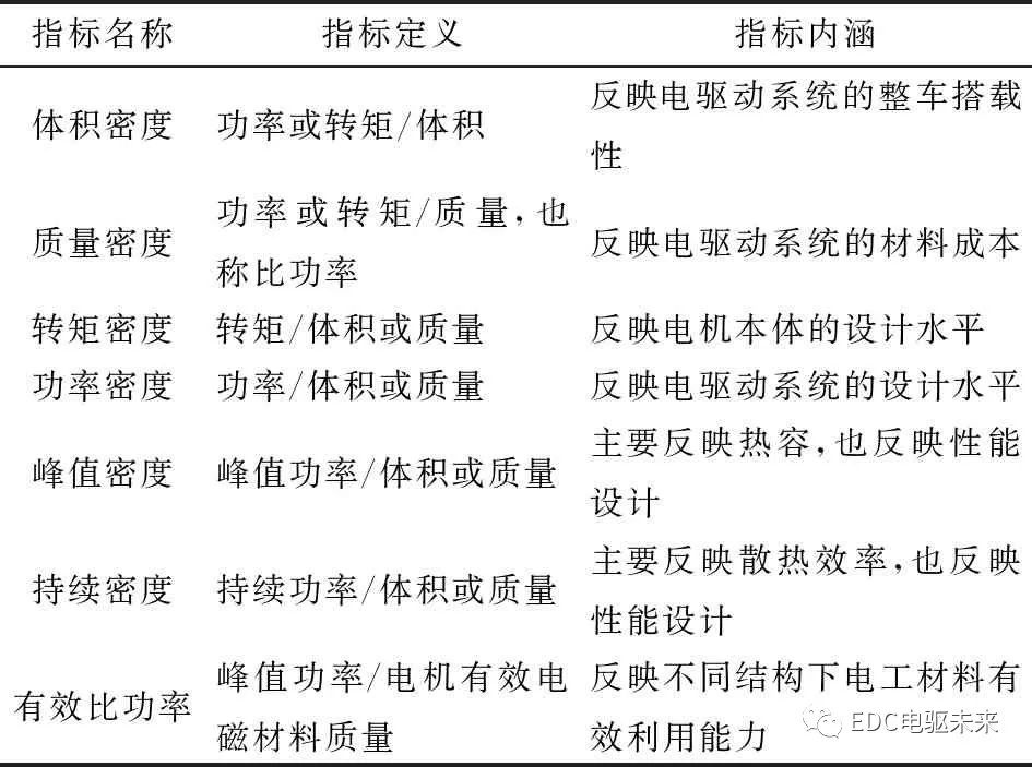
Generally, the electric drive system is evaluated by the mass power density index, the motor body is evaluated by the effective specific power index, and the inverter is evaluated by the volume power density index; the general passenger car power system is evaluated by the power density index, while the commercial vehicle power system is evaluated by the torque density Index evaluation.
The evaluation of power density index needs to be carried out under certain preconditions, which is closely related to factors such as index definition, evaluation object, operating voltage, operating temperature and its cooling conditions, duration, constant power speed regulation range, etc. The quantitative index of power density under different premise The difference is huge. Due to the absence of uniform standards, various companies tend to inflate high indicators to improve market competitiveness when promoting products. In response to this situation, during the compilation process of the national "Energy Saving and New Energy Vehicle Technology Roadmap 2.0", a normative definition was put forward for the effective specific power index of the motor:
Effective mass of the motor: the mass of the stator and rotor assembly, including insulation and curing materials, excluding shafts, shells, etc.;
Duration corresponding to peak power: 30 s;
Definition of peak power: within the range of base speed to 0.75 times the maximum operating speed, the maximum power that can be output for 30 s;
Current level: converted to 450 A;
Voltage level: converted to bus voltage 400 V;
Test environment: 85°C environmental chamber, 65°C coolant inlet temperature [1] .
2 Technical path
Based on the above theoretical analysis, focusing on improving system integration and lean matching design, increasing speed and voltage, optimizing design of new motor and electromagnetic performance, new power electronics and control technology, innovation and upgrading of materials and processes, etc., by increasing peak output power and reducing The three technical paths of volume and quality, improving thermal design and thermal management can realize the improvement of the power density of the motor drive system. The carding technology framework is shown in Figure 1.
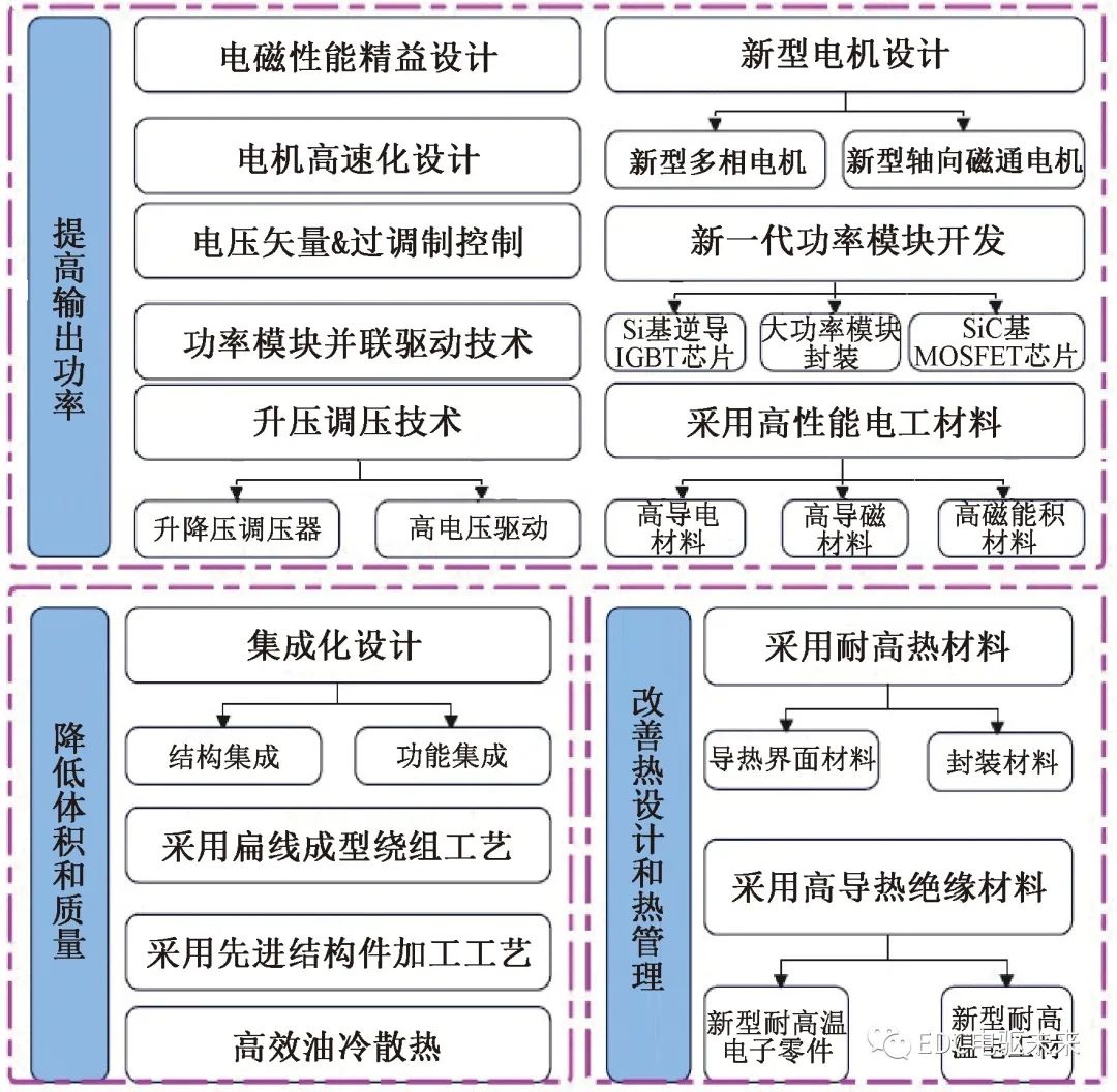
Figure 1 High power density electric drive technology shelf
2.1 Increase output power
2.1.1 Lean Design of Electromagnetic Performance
Compared with other types of motors, permanent magnet synchronous motors have advantages in power density and efficiency, and are suitable for traction drives of electric vehicles. Assuming that the main magnetic flux is the same, the permanent magnet torque is the same, and the permanent magnet synchronous motor with built-in structure can use the newly added reluctance torque to further improve the total torque output capability. The permanent magnet synchronous motor torque of the surface mount structure is only composed of the permanent magnet torque, see formula (1). The permanent magnet synchronous motor torque of the built-in structure is composed of two parts: permanent magnet torque and reluctance torque, see formula (2) [2] . Based on the actual working conditions of the vehicle, the electromagnetic structure can be finely designed, the electromagnetic load can be reasonably distributed, and the parameters of motor pole pairs, permanent magnet flux linkage, direct axis inductance, quadrature axis inductance, and phase resistance can be adjusted to obtain ideal power output characteristics.

In the formula: T e is the electromagnetic torque; p is the number of pole pairs; ψ f is the flux linkage generated by the permanent magnet; i s is the stator current; β is the space electrical angle; L d is the d- axis inductance; L q is the q- axis inductance.
By comprehensively adopting the electromagnetic structure design of "asymmetrical rotor + concentrated winding + unique magnet gap", Mitsubishi Electric has achieved a motor output power density of 23 kW/L, especially for one direction of rotation to maximize the power density, as shown in Figure 2 shown.
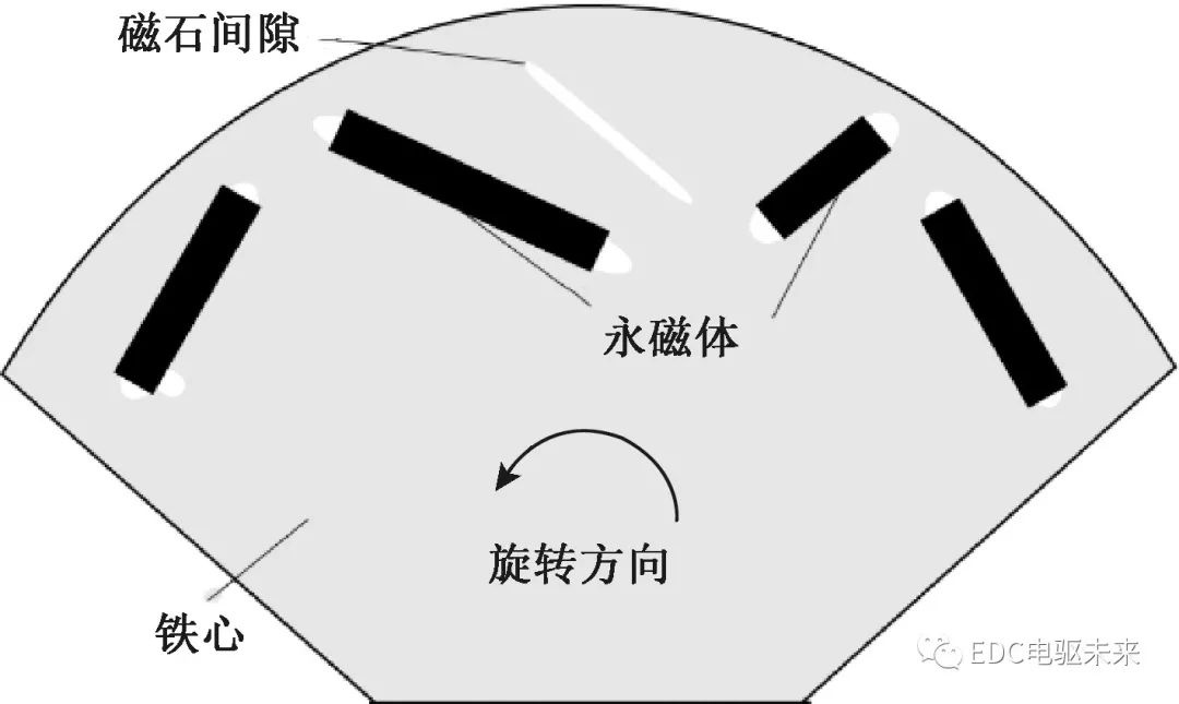
Figure 2 Mitsubishi high power density motor asymmetric rotor electromagnetic structure
2.1.2 Motor high-speed design
According to the motor design formula (3), under the premise of the same power, the higher the speed, the smaller the torque, the smaller the motor size D 2 L , the lower the material consumption, and the lower the cost, the higher specific power can be achieved.
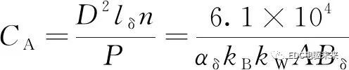
(3)
In the formula: C A is the motor constant; D is the inner diameter of the stator; n is the speed ; α δ is the pole arc coefficient; l δ is the effective length of the iron core ; Density (magnetic load); A is the line load (electric load), which is the number of turns per phase; m is the number of phases; I is the current value.
The key technology of high-speed motor is: in order to control stability, higher control frequency and computing power are required, the hardware execution speed of the main control chip is required to be faster, and the software function design is optimized; At the same time, design system protection functions, such as active short circuit, etc., to improve system safety; high-speed motors need to use ultra-thin silicon steel sheet and magnetic steel section design to suppress iron loss; high-speed motors need to adopt high-strength rotor electromagnetic structure , high-speed bearings, high-strength silicon steel and other designs to achieve, as shown in Figure 3.
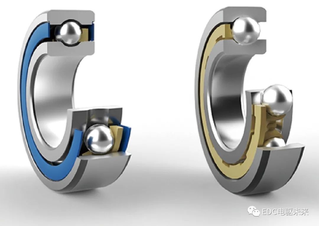
Figure 3 SKF's new high-speed ball bearing HSBB 1.8 [4]
2.1.3 New multi-phase motor design
A multi-phase motor refers to a motor with more than 3 power supply phases. Under the same bus supply voltage, the current output capability is improved, thereby improving the power output capability. It is especially suitable for application scenarios where the supply voltage is limited and the power demand is relatively large. By increasing the number of phases, the input torque ripple of the motor is reduced, and the NVH characteristics are improved. At the same time, problems such as dynamic and static voltage equalization in the two-level inverter can be avoided, and the reliability of the electric drive system can be improved [4 ] . Compared with traditional three-phase motors, multi-phase motors have the advantages of small torque ripple, high torque density, high power at low voltage, and high fault-tolerant reliability [4-6] . Figure 4 is a comparison of the stator structure of a certain multi-phase motor and a traditional three-phase motor.
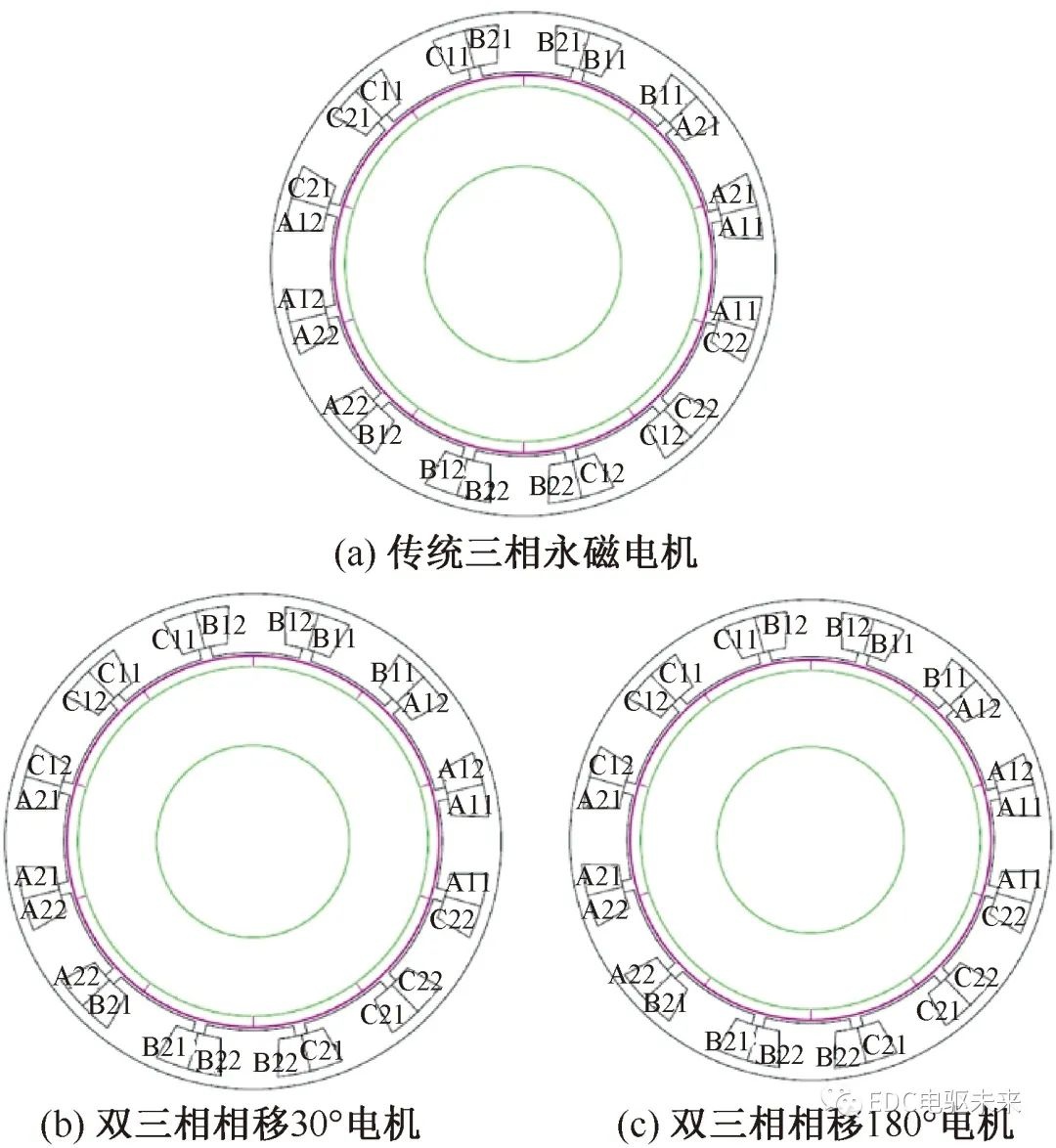
Fig.4 Winding distribution in the actual slot of surface-mounted 12-slot 10-pole permanent magnet motor
2.1.4 New Axial Flux Motor Design
Axial flux motor, also known as disc motor, has a flat air gap and the direction of the excitation magnetic field is parallel to the motor shaft. Compared with ordinary radial motors, the rotor of axial flux motor has a larger diameter. It can be seen from the torque formula that under the same force, the rotor diameter increases to obtain greater torque, which also means that the axial flux motor has a stronger torque when the permanent magnet material is the same as the copper wire material Output capacity [7] . Generally, the new axial motor structure can bring about a 30% increase in torque capacity compared with the traditional radial motor structure [7] . Due to its structural characteristics, the axial flux motor has the characteristics of compact axial structure, flat shape, small volume, and high power density. After continuous improvement and perfection in the industry in recent years, it has gradually been suitable for new energy electric vehicles [ 7-8] . Figure 5 is a comparison of the structure and magnetic circuit between the traditional radial flux motor and the new axial flux motor.
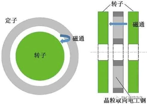
Figure 5 Comparison of traditional radial flux motor and new axial flux motor
2.1.5 Voltage Vector Overmodulation Control
Compared with the torque control method based on the current vector, the voltage vector control does not need to reserve the margin of the voltage closed-loop regulator, and has a natural field weakening capability. The same bus voltage can achieve a deeper field weakening depth and fully tap the maximum output of the motor ability. The comparison of various voltage vector control schemes is shown in Table 2.
Table 2 Introduction to the characteristics of the voltage vector control scheme [10]
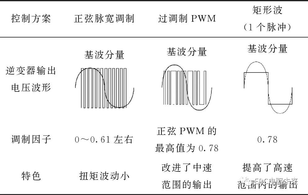
The operating range of SVPWM is extended to the hexagonal area by overmodulating the PWM strategy, as shown in Figure 6. Combined with the voltage vector control method, the utilization rate of the DC bus voltage is increased from 1 to 1.15, and the output torque and power of the motor system can be greatly improved by maintaining the bus voltage [9-11] .
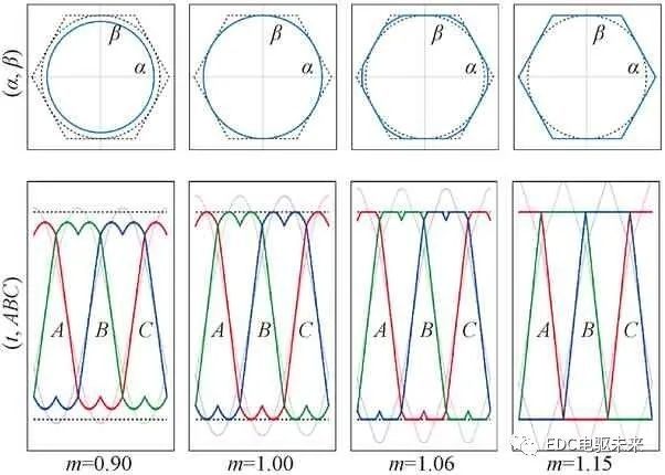
Figure 6 PWM overmodulation strategy
2.1.6 Development of a new generation of power modules
1) Development of new power devices
Compared with traditional Si-based IGBT technology, the latest generation of automotive-grade Si-based reverse conduction IGBT technology has the characteristics of miniaturization, low cost, high power density, and high reliability. Adopt technologies such as increasing the working junction temperature of the module, moderately boosting the voltage, integrating temperature and current sensors on the chip, and reverse-conducting chips to increase the power density during the period and reduce the module volume and cost [9,11 ] . Figure 7 is a schematic diagram of Fuji M653 reverse conduction IGBT technology.
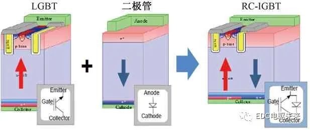
Figure 7 Fuji's latest generation of Si-based reverse conduction IGBT technology
The next-generation SiC-based MOSFET chip has the following technical advantages: high band gap (SiC=3Si), stable operation under high pressure and high temperature, ~600 ℃; high electric field strength (SiC=10Si), low on-resistance, high voltage resistance, high efficiency ; High electron saturation rate (SiC=2Si), fast switching speed, frequency ≥ 10Si; high thermal conductivity (SiC=3Si), good heat dissipation performance, high temperature resistance; melting point (SiC=2Si), high temperature resistance operation; unipolar device , no tailing current, low turn-off loss. The reasons why it has not been widely promoted at present are: the production process is immature, the cycle is long, the yield rate is low, and the cost is high; the control frequency is high, the false conduction rate is high, and there are many technical problems in electromagnetic interference and insulation. The comparison of power device characteristics is shown in Figure 8.
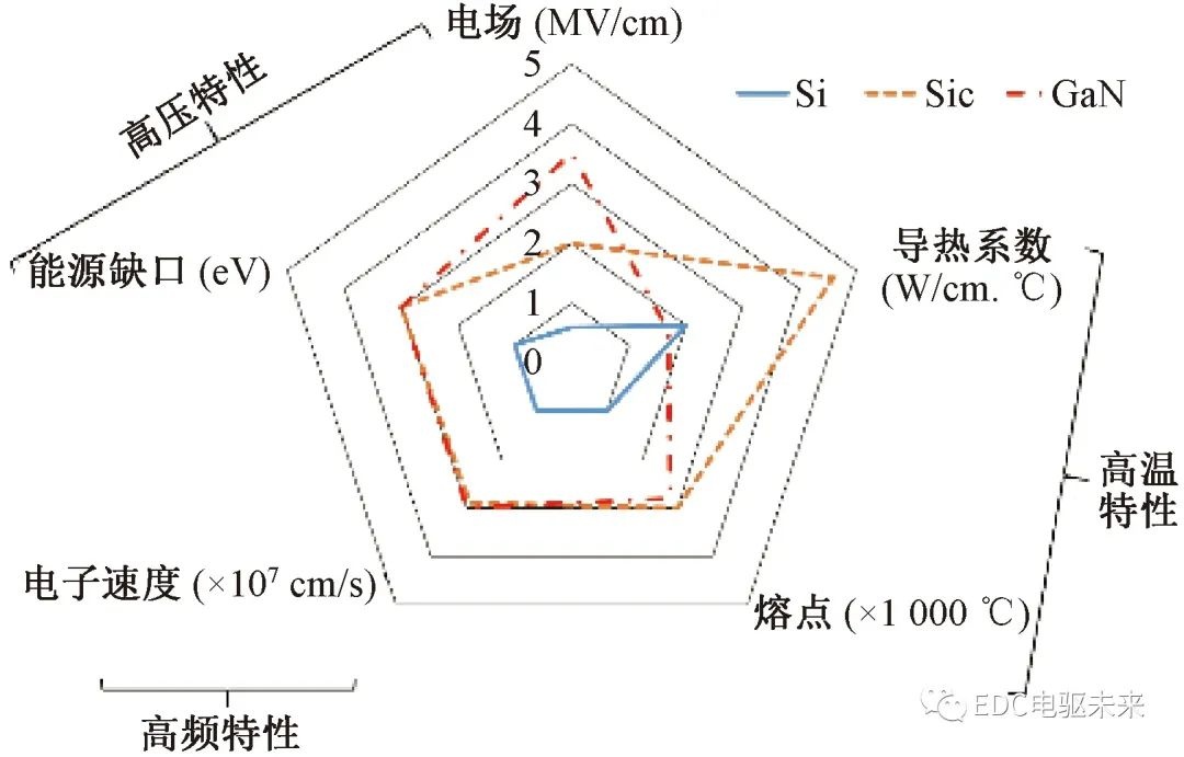
Figure 8 Comparison of power device characteristics
2) New high-power module packaging technology
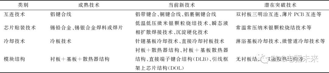
The development trend of power modules in the future is to seek higher chip junction temperature, higher heat dissipation efficiency and reliability, lower parasitic inductance, and a module structure that tends to be miniaturized and integrated. The current research focus of new high-power module packaging technology mainly focuses on interconnection, mounting, heat dissipation and module structure, as shown in Table 3.
Table 3 Development trend of power module packaging technology for hybrid/electric vehicles [12]
2.1.7 Parallel drive technology of power modules
Three ways to increase the power output level of the power module: ①Directly select higher power level devices; ②Use low power level devices in series to increase the voltage level; ③Use low power level devices in parallel to increase the current level. The voltage platform in the application of electric vehicles is generally not high, so the parallel connection method of power modules is often used to improve the current output capability and then the power output capability [13] . The parallel drive of power modules is generally affected by factors such as the difference of parallel IGBT parameters, the consistency of the drive circuit, the layout of the main circuit, and the unbalanced heat dissipation [14] . Parallel drive of power modules generally requires the selection of IGBT modules with positive temperature relationship characteristics. The higher the temperature, the higher the V CE , and the current unevenness will be automatically adjusted. When the temperature rises, the current I c will decrease, which is suitable for parallel connection. A well-known case in the industry for parallel drive of power devices is the Tesla Model 3, which uses a four-parallel structure of SiC discrete devices customized by ST, and realizes heat dissipation and water cooling through copper substrates, as shown in Figure 9[ 13-18 ] .
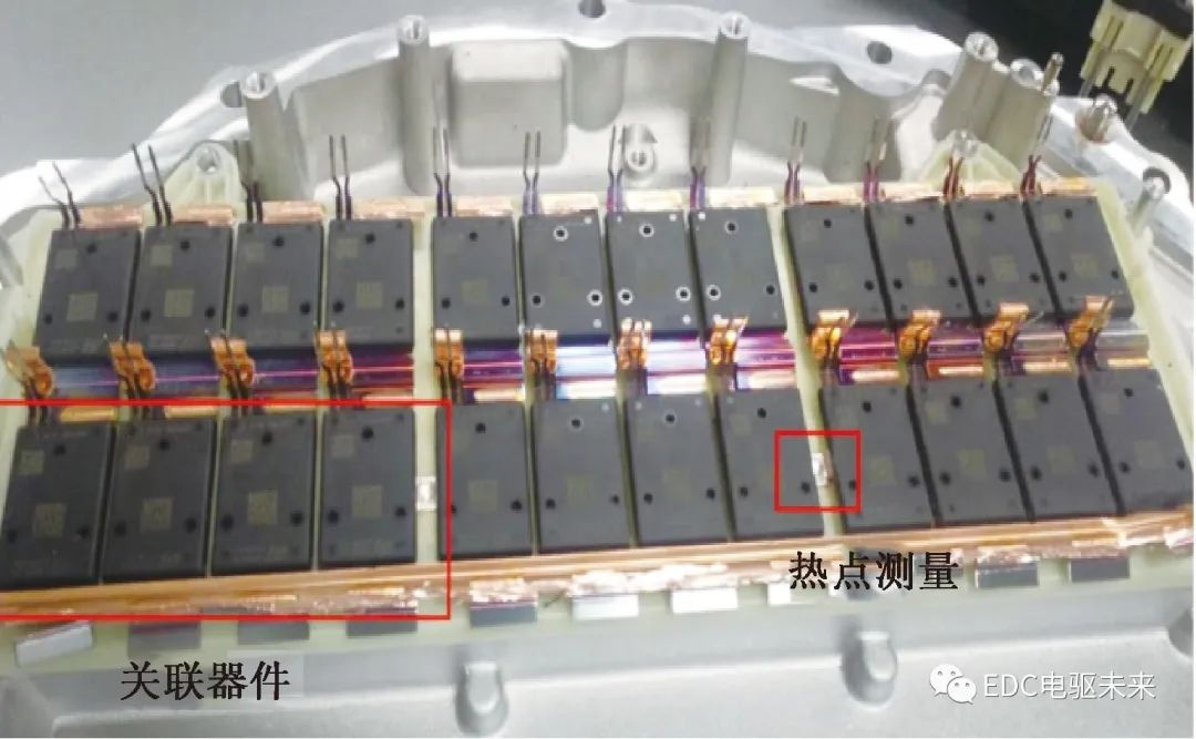
Figure 9 Parallel connection scheme of Tesla power devices [13-18]
2.1.8 Boost voltage regulation technology
A three-phase full-bridge inverter cascaded booster is added between the power battery and the inverter circuit. The boost inverter can adjust the working voltage of the DC terminal in real time according to the load, improve the output power of the electric drive system, and reduce the Reduce current and loss, realize light weight and low cost. Booster voltage regulation technology makes it possible to balance the pursuit of efficiency and power [19-21] . It should be noted that the direct use of high-voltage batteries for power supply and the design of high-voltage motors can also significantly improve the power output capability. The voltage development trend of the electric drive system is shown in Figure 10.
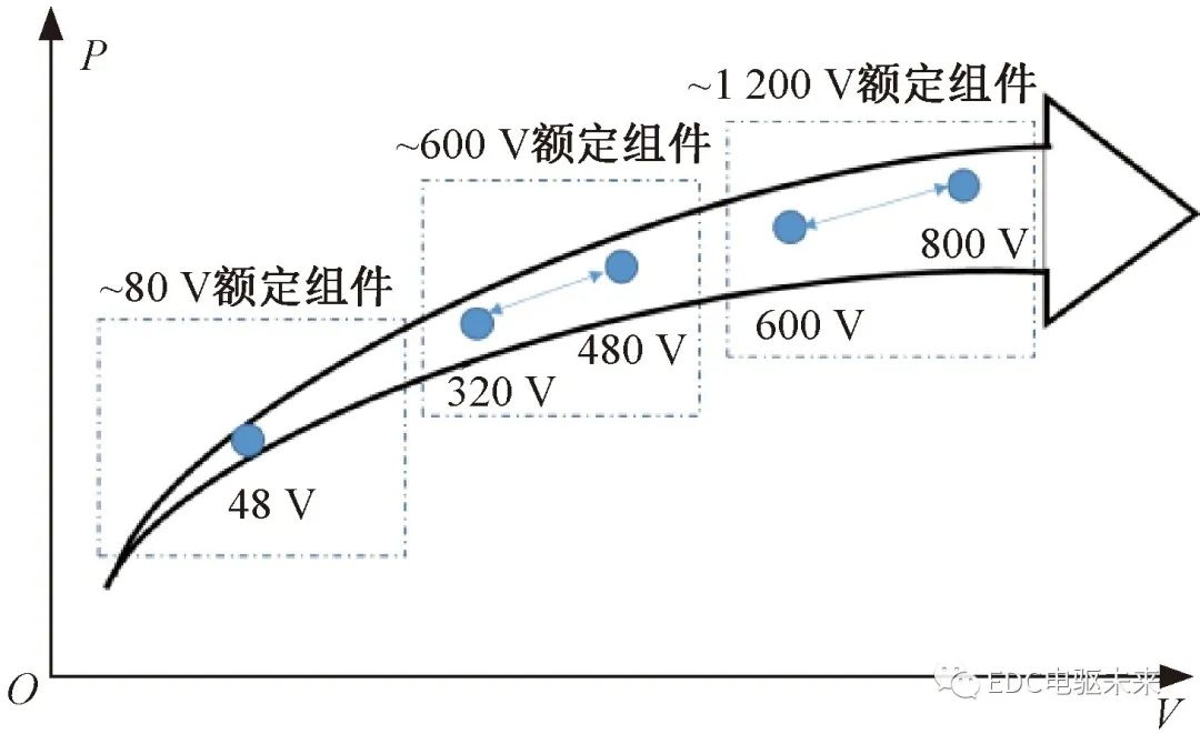
Figure 10 Voltage development trend of electric drive system
2.1.9 Use of high-performance electrical materials
In order to meet the requirements of high torque density and high power density for new energy vehicles, permanent magnet materials with large coercive force, residual magnetic flux density and maximum magnetic energy product should be selected when designing the motor, and high power density temperature rise should also be considered problem, fully consider its temperature resistance [22] .
Silicon steel should be made of thin sheet materials with high magnetic permeability and low loss. The motor with high power density has high speed and high power supply frequency. Iron loss is the main source of loss.
The wire should choose enameled wire with higher heat resistance level (above 240 ℃), or choose wire with lower loss. At present, the maximum temperature resistance of enameled wire is 220 ℃, which is relatively scarce, but Hitachi can achieve 240 ℃. Figure 11 shows the selection of Hitachi wire materials.
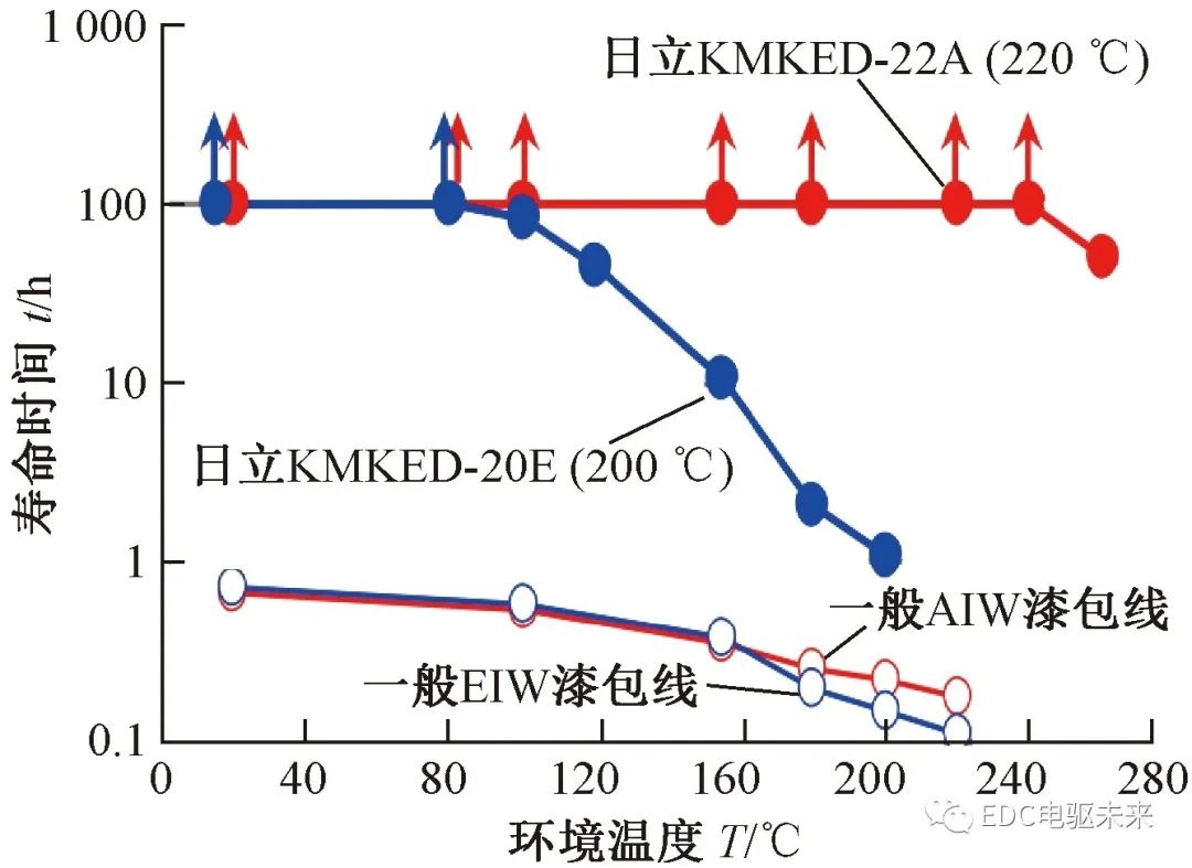
Figure 11 Selection of high temperature resistant wire
Figure 12 shows the rotor of a Tesla cast copper induction motor. Considering that the drive motor for electric vehicles is powered by a frequency converter, it uses a copper guide bar, which can meet the requirements for the starting performance of the motor, and at the same time ensure that the motor has a high efficiency [ 22] .
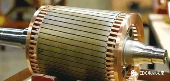
Figure 12 Tesla cast copper rotor
2.2 Reduce volume and quality
2.2.1 Integrated design
1) Structural integration
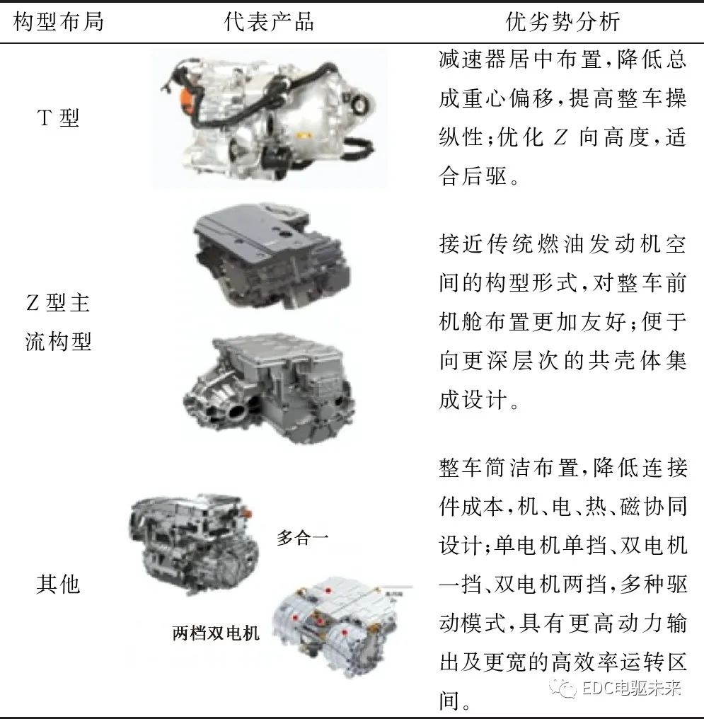
According to different configurations, the layout and coupling methods of vehicle motors are various: it can be integrated with the engine, clutch, transmission, drive shaft, drive axle, wheel hub, etc.; the EV electric drive assembly on the market, according to the motor shaft Different from the layout of the output shaft of the reducer, it can be divided into parallel shaft and coaxial integrated structure. According to the layout position of the inverter, it can be divided into axial inverter and radial inverter integrated structure; component level The integration dynamics include metal insert integration, embedded component PCBA technology, gate drive chipset integration, sensor custom development, etc. Table 4 shows the commonly used integrated design schemes for electric drive systems.
Table 4 Commonly used electric drive integration design schemes
2) Function integration
Shared control chip (domain controller), shared power device topology (charger, DC/DC, inverter integration), etc. Figure 13(a) shows BYD's motor winding and power device multiplexing charging technology, and Figure 13(b) shows Huawei's power device multiplexing charging technology.
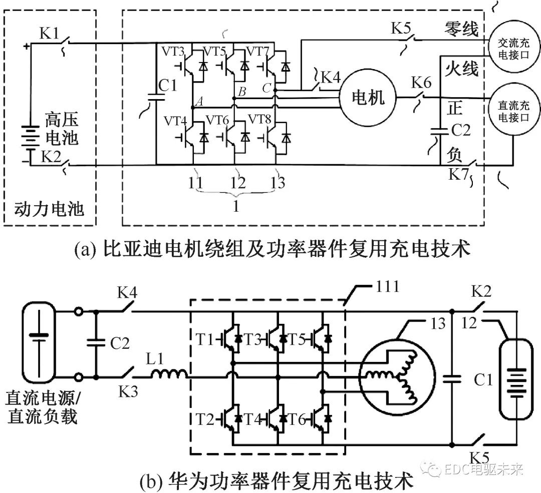
Figure 13 Motor winding and power device multiplexing charging technology [23-24]
2.2.2 Using flat wire forming winding process
The advantages of the flat wire winding process lie in the following aspects.
① Miniaturization: high slot fill rate, short end, high power density;
② High performance: good heat conduction, low temperature rise, high continuous power;
③ Good craftsmanship: suitable for mass automated production;
④Good NVH performance and good structural rigidity;
⑤ Optimize the distribution of efficiency zones, suitable for urban working conditions.
The disadvantages of the flat wire winding process lie in the following aspects.
①The skin effect at high speed leads to an increase in loss, and the higher the frequency, the greater the loss;
② High quality requirements for copper wire raw materials, easy to damage;
③The process is complicated, the precision is high, and the scale depends on professional high-end equipment;
④Serialized design is difficult to realize, and design flexibility is insufficient.
2.2.3 Adopt advanced structural parts processing technology
1) Hollow shaft rotary forging process
With the further improvement of lightweight requirements, the integrally forged hollow shaft will be gradually applied. Its main technical advantages are: substantial weight reduction; reduced machining cost; ideal fiber streamline and material properties; low moment of inertia.
2) Shell semi-solid casting process
The requirements of the electric drive system for aluminum alloy shell parts are light weight, excellent mechanical properties, good sealing, good heat dissipation, and low cost. As the shape of parts becomes more complex and the wall thickness becomes thinner (lighter), traditional die casting becomes more and more difficult to meet the needs of product applications. Semi-solid injection molding technology combines the advantages of solidification processing and plastic processing, and has the characteristics of high precision, energy saving, environmental protection, and high safety. During molding, fine alloy particles are loaded into the hopper, and the material is heated by the feeding cylinder of the machine to become semi-solid. Molten state, injection molding [25-26] . The technical characteristics of semi-solid rheological aluminum alloy castings are high density of formed parts, thick or thin wall thickness (less than 1 mm), high dimensional accuracy, good mechanical properties, good thermal conductivity, and less porosity and shrinkage (parts The porosity is less than 0.069%), the surface quality is high, and the mold life is long, as shown in Figure 14.
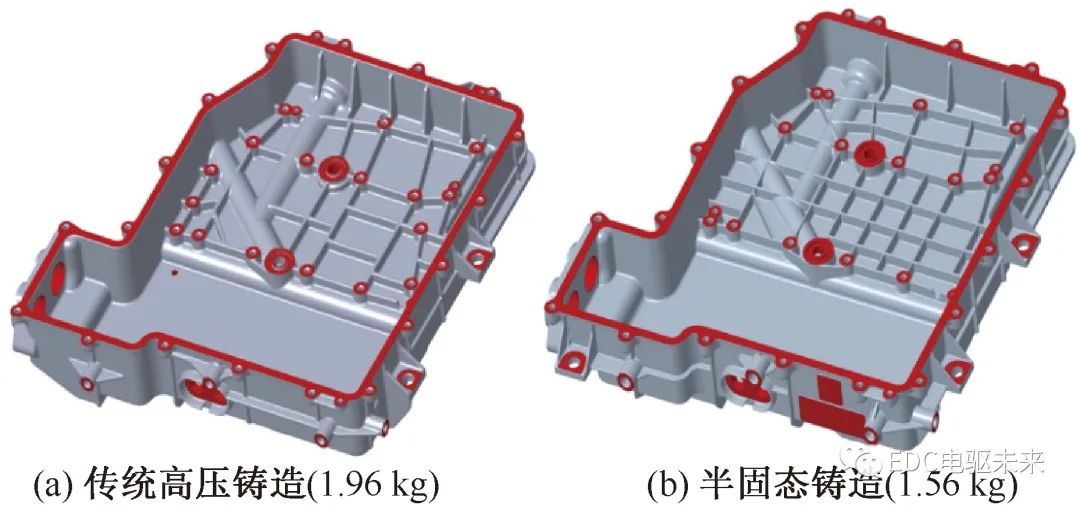
Figure 14 Shell process comparison
3) Integrated casting process of shell and lightweight design of rotor core
The motor housing adopts an integrated casting water jacket, which can reduce the cost and improve the rigidity and mode of the housing, as shown in Figure 15.
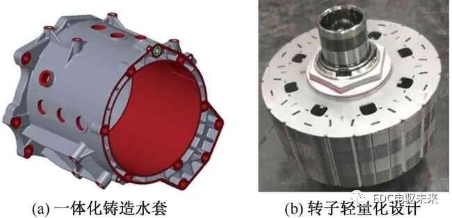
Fig. 15 Process design of advanced motor structure
2.3 Improve thermal design and thermal management
2.3.1 High-efficiency oil cooling
Enhanced cooling can reduce temperature rise, reduce copper wire resistance, reduce copper loss, reduce temperature loss of permanent magnet magnetic properties, increase power output, and thus improve efficiency; after enhanced cooling, higher electromagnetic load can be used to increase power density ; The efficiency and power density of the motor are taken into consideration [27-28] .
2.3.2 High thermal conductivity materials
In order to increase the power density of the motor, it is necessary to reduce the thermal resistance of the motor package, reduce the space and cost of the motor, and realize the high speed of the motor while maintaining good reliability and stability. This requires improving the thermal conductivity of the motor packaging material (thermally conductive epoxy, filler, winding insulation, etc.) and reducing contact thermal resistance.
Thermal interface materials (TIM) are based on polymer systems and manufactured with advanced filler technology, which can handle critical heat dissipation issues and have long-term reliable performance, and are applied between the heat source and the surface of the heat sink (cold plate, finned heat sink, etc.) , Exclude air with high thermal resistance, make the heat transfer surfaces in close contact, improve heat uniformity and heat conduction rate, and help realize weight reduction.
2.3.3 High heat-resistant materials
High heat-resistant materials can improve the environmental tolerance of components and help to take advantage of the high-temperature operating characteristics of the next generation of wide-bandgap semiconductors. For example, the DC-link capacitor currently widely used in mass production is based on polypropylene winding technology, and its maximum temperature resistance is only 105 °C, which is the shortest temperature-resistant board for inverters.
Recently, the solid capacitor technology developed by PolyCharge—NanoLam TM , as shown in Figure 16, uses thin polymer dielectrics to produce self-healing high-voltage capacitors, which are half the size and quality of current capacitors and have higher temperature resistance. (140 ℃), higher energy density, more stable capacity, lower equivalent series resistance and equivalent series inductance.
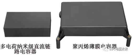
Figure 16 NanoLam high temperature film capacitor
 XINDA
XINDA