![]()
Technical analysis of flat wire motor for new energy vehicles! 6 core manufacturing processes of flat wire motor stator!
With the year-by-year development of the new energy vehicle industry, the production and sales of electric vehicles have exploded, and the demand for high-performance and high-efficiency motors is also increasing. kg, further promoting the pursuit of higher power density of the motor. The high efficiency, light weight, miniaturization and low cost of the electric drive system are the future trends; while the integration of the electric drive system and the flattening of the motor are the main technical routes to achieve light weight and miniaturization. The flat wire winding has developed rapidly due to its unique advantages compared with the round wire winding, and has become a hot spot in the research and development of new energy vehicle motors. Flat wire motors are also widely used at home and abroad, and the penetration rate of flat wire motors for new energy vehicles is increasing year by year. This paper will briefly introduce the flat wire winding technology, compare and analyze the advantages of the flat wire motor, introduce the manufacturing process of the Hair-pin motor, summarize the new technologies and new processes of the flat wire motor application in recent years and the future optimization research direction, and provide a basis for the research of the flat wire motor. for reference.
1 Brief introduction of flat wire motor technologyBar-wound motor (Bar-wound motor) is used to be called flat wire motor in China. Flat wire motor technology means that the stator of the motor uses flat copper wire windings to replace the original round copper wire windings. The general term for technologies such as rotor structure optimization, cooling scheme optimization and control optimization. The flat copper wire winding refers to the change in the slot structure of the motor stator, and at the same time, the small and thick rectangular wires are replaced by the original many and thin round wires as the windings. Flat wire motors are widely used in the field of new energy vehicles due to their advantages of small size, high slot fill rate, high power density, good NVH performance, and better heat conduction and heat dissipation performance.2 Comparison of flat wire motor and round wire motorMotor energy loss mainly includes motor copper loss, motor iron loss, wind friction loss and stray loss, of which motor copper loss accounts for nearly 70%. Reducing motor copper loss can greatly reduce motor energy loss and improve motor power density. The calculation formula of DC copper loss is shown in formula (1). The rectangular copper wire used in the flat wire winding has a significant change in cross-sectional area compared with the round copper wire winding, which can effectively reduce the winding resistance and thus reduce the copper loss. At the same time, the rectangular wire winding has a smaller gap between the flat wires than the thin round wire winding, and more winding copper wires can be installed under the same stator slot volume, so it has a higher slot filling rate. The slot full rate of the round wire motor is about 40%, while the full rate of the flat wire motor can be as high as 70%. Under the high slot full rate, the copper wire filling of the flat wire motor with the same motor power is less, and the size of the stator core and the end is reduced. The size of the motor is also smaller, and the power density of the motor is further improved while saving materials.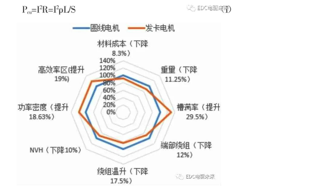
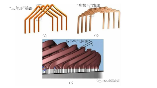
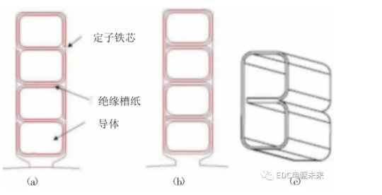
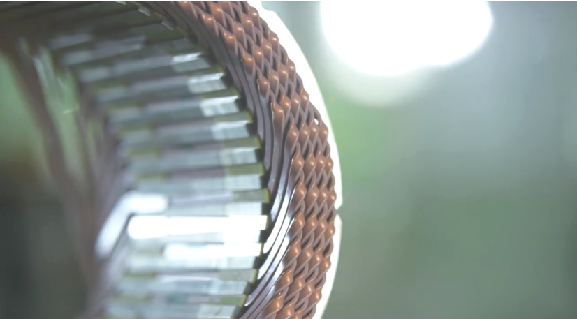
Figure 1 Comparison of the performance of the round wire motor and the hairpin motorCompared with the round wire motor, the stator of the flat wire motor has a smaller slot size, which can effectively reduce the cogging torque and thus reduce the electromagnetic noise. At the same time, the rectangular wire is more rigid and can also suppress the noise of the armature. Optimized to have better NVH performance [1] .The winding end of the flat wire motor is wound into special shapes, such as wavy, triangular, stepped, etc., as shown in Figure 2, which effectively reduces the size of the winding end, which is beneficial to achieve miniaturization and light weight [2] . At the same time, the rectangular conductor makes the internal space less, the contact area between the conductor and the conductor and the conductor and the core slot is larger, and the heat conduction and heat dissipation performance are better. There is a minimum air gap between the conductors at the ends of the windings, which is more convenient for heat dissipation. At the same time, with the oil injection cooling technology at the end, the heat dissipation performance of the flat wire motor is further improved; under the condition of lower temperature rise, the whole vehicle has better acceleration performance and effectively improves the high temperature power of the vehicle. sex.Figure 2 Winding end diagram of flat wire motorFlat wire motors also have shortcomings, which are greatly affected by the skin effect. The skin (skin) effect guides that when there is alternating current or alternating magnetic field in the body, the current distribution inside the conductor is uneven, and the closer to the surface of the conductor, the greater the current density; it reduces the effective energized copper wire area and increases the equivalent resistance of the winding. High frequency AC losses increase. The length-to-width ratio, placement direction, and equal division of the conductors all have an impact on the skin effect, and the skin effect is more serious in the same-slot winding than in the same-slot winding. Under the same slot depth and slot width, increasing the number of conductor layers is beneficial to reduce the skin effect, reduce the AC loss of the motor at high speeds, and improve the motor performance. Another limitation of the development of flat wire motors is that their automatic production lines are expensive, which is 2-3 times that of round wire stator automatic production lines, and the company invests a lot in the early stage.3 Classification of flat wire motorsAccording to the product type, flat wire motors can be divided into concentrated winding flat wire motors, wave winding flat wire motors and Hairpin (hairpin) flat wire motors. Among them, the hairpin flat wire motor technology is the mainstream technology that is widely used.The concentrated winding is made of flat copper wire to form a single-tooth winding, as shown in Figure 3(a), and another tooth is installed corresponding to a single-tooth winding, because the short-span coil end can effectively reduce the end size, and its process is similar. Also simpler than Hairpin flat wire motors. Due to the excessive fractional harmonics, this structure has the disadvantages of large torque pulsation and complex radial force; in order to reduce the cogging torque and torque pulsation vibration, the structure needs to ensure roundness, uniformity in the assembly process. The axial degree and the uniform distribution between the teeth, the assembly requirements are higher. Concentrated winding technology is widely used in the field of industrial motors, and some manufacturers in the field of new energy vehicle motors are also researching and applying it; for example, Honda has adopted this technology in its Acura hybrid model, with its unique fractional slot concentrated winding, split lobe The stator structure and related optimization techniques have achieved good results. The Songzheng 270 series PHEV-P2 motor using concentrated winding technology is shown in Figure 3(b), which is used in hybrid solutions with its unique advantages.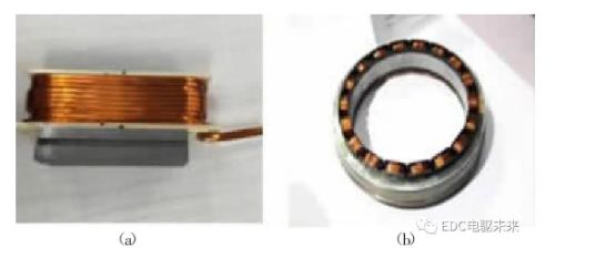
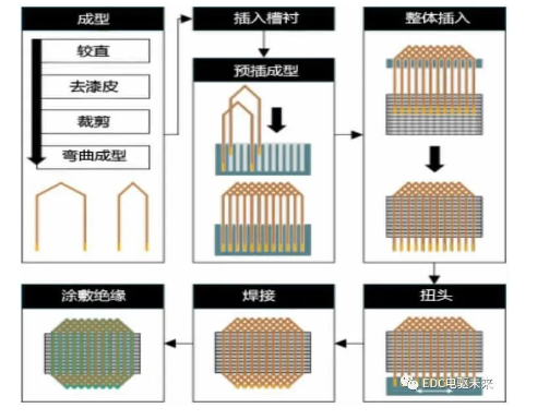
Figure 3 Concentrated winding flat wire motor diagramThe wave winding flat wire motor adopts continuous winding of the winding to be integrally formed and inserted, or inserted into the stator slot while winding to form a wave-shaped end. Compared with the Hairpin flat wire motor, it has no solder joints, which can further shorten the height of the winding end and reduce the Motor size. However, this type of stator assembly has a wider slot size, which makes the cogging torque larger, the torque ripple is higher, and the NVH performance is poor. It needs to be optimized with electromagnetic multi-objective optimization design and other measures. At the same time, its production cost is higher than that of Hair. -pin motor is higher.Hair-pin (U-pin) is also called hairpin winding because its winding shape is similar to "hairpin". One end of the enameled flat copper wire is pre-shaped into a U shape, and then inserted into the stator core slot, and the other end is twisted and processed into frog legs. shape, and then welded together to form a wavy winding [3] . Another I-PIN winding process directly inserts the straight copper wire into the stator core slot, and then twists the two ends into a frog leg shape and welds them together to form a wave winding, eliminating the need for the pre-forming process in the U-PIN winding. . U-PIN and I-PIN flat wire windings belong to the second generation of axial embedded windings. Compared with the two, the highest efficiency and peak torque are comparable, but the latter has a higher slot full rate than the former. Continuous torque and continuous power; with double the number of solder joints in the latter, the winding end size is slightly increased, and the risk of joint failure is also higher. Hair-pin winding process is a process route widely used at home and abroad.The card issuing technology is a large-scale, high-quality, low-cycle stator production technology. The process chain mainly consists of the following five steps: forming (straightening, stripping, cutting, bending of enameled copper flat wire), inserting (stator slot) slot lining and hairpin coil combination insert), twist, welding and insulation [4] . A schematic diagram of the process steps is shown in Figure 4.Figure 4 Process step diagramIn addition to the insulating paint film insulation between the copper wires of the hairpin winding, a stator slot lining is added to separate the conductors from each other, so as to eliminate the direct contact between the turns or the conductor and the stator core, improve the insulation performance and enhance the short circuit protection. Therefore, it is necessary to insert insulating slot paper. Common slot paper shapes are O-type, C-type, B-type, S-type, etc., as shown in Figure 5. The B-groove lining eliminates the gap at the corner of the S-groove lining and enhances the protection against short-circuit faults [5] .Figure 5 Insulation slot paper slot diagramIn the paper insertion process, the insulating slot paper is inserted into the stator slot in advance. With the increase of the number of flat conductor layers, the process difficulty also increases greatly. The PIN forming process includes stamping forming, spring machine and CNC automatic forming, etc. The former has fast forming speed, low cost but greater damage to copper wire, and the latter has good versatility and small damage to copper wire but high equipment cost. After the PIN is formed, it is pre-inserted into the profiling tooling. With the increase of the number of layers of the flat wire, the difficulty of automatic insertion of the transconductor also increases. Then, all the PINs in the profiling tooling are inserted into the iron core as a whole to the corresponding design size. This process requires high precision of the equipment. Then through the process of flaring, twisting and cutting, the ends of the windings are flattened for welding. At present, TIG welding and laser welding are the most popular flat wire motors, and other companies are also experimenting with welding methods such as CMT cold welding. After the welding is completed, it is necessary to conduct electrical performance testing, phase resistance and phase inductance and its balance testing, and withstand voltage and resistance testing of the windings, and then apply the coating after passing the testing. The coating process is divided into powder coating and liquid coating according to different coating materials. The process sequence of the two is different. Powder coating is applied first with dipping paint, and liquid coating is first dipped paint and then coated. According to different materials, the dipping process includes traditional dipping, vacuum dipping, vacuum pressure dipping, drip dipping, EUV dipping and so on.
5.1 The number of conductor layers increases gradually
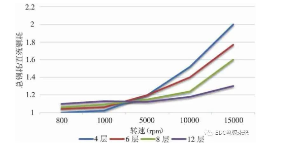
As shown in Figure 6, increasing the number of conductor layers can effectively reduce the AC copper loss, thereby reducing the total copper loss of the motor and improving the overall performance of the motor. In order to further reduce the high-speed AC loss caused by the skin effect, the card issuing motor adopts the method of increasing the number of conductor layers to optimize, from the 4-layer, 6-layer, and 8-layer schemes that have been applied to the 12-layer and 16-layer schemes that are being studied. The number of conductor layers tends to increase gradually. The research difficulty is mainly in the control of process level and manufacturing cost [6] .Figure 6 Comparison of copper loss of multilayer conductors
5.2 Optimizing Insulation
The more complex insulation groove paper makes the installation process steps more complicated, and at the same time, the precision of CNC installation equipment is also higher, and the research on better insulation technology has become an important direction. The Chevrolet Bolt motor simplifies the insulating slot liner and uses a simpler two-piece slot insulation to protect the windings from shorting to the stator core. The new design is shown in Figure 7(a), compared with the S-type B-type insulating slot liner, it eliminates the insulation between conductors, further improves the slot full rate, and simplifies the stator manufacturing process. At the same time, in order to minimize the voltage potential between the wires in the slot, GM has optimized the winding layout. There is also a polymer insulation layer on the conductor base insulation layer, as shown in Figure 7(b), so as to save the slot lining, solve the problem of winding inter-turn insulation, and simplify the production process [2] .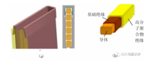
5.3 Widespread use of oil cooling technology
The heat of the winding needs to be taken away by the water through the long path of the insulating layer in the slot - the stator core - the casing, and the thermal resistance existing during the period is easy to form local hot spots, which makes the water cooling method inefficient. Oil cooling can directly contact the heat source and has no effect on the magnetic circuit of the motor. Oil cooling technology with higher heat dissipation efficiency has become a research hotspot. The main heat of the motor is concentrated at the end of the winding, and the unique end oil spray cooling of the flat wire motor can better achieve heat dissipation. The technologies of oil circuit cooling, oil injection cooling, shaft oil throwing cooling and stator closed oil circulation cooling have been widely applied and studied on flat wire motors.
Six core manufacturing processes of flat wire motor stator
The basic production process of flat wire motor stator production is slot paper → manufacturing hairpin → hairpin → end ring shaping → end ring welding → star point → welding insulation treatment, including wire forming and paper forming and inserting paper, these two The processes are performed synchronously.
1. Paper insertion process
Insulation paper is arranged between the stator slot and the conductor of the flat wire motor to ensure the insulation between the out-of-phase conductors and between the conductor and the stator core.Generally speaking, the paper insertion process of flat wire motor mainly includes paper forming, paper cutting and paper insertion. Common slot paper forming processes include cold forming and thermoforming.Regarding the shape of paper, there are mainly O-type, C-type, B-type, and S-type. The common type is O-type. B-type and S-type can significantly improve the insulation performance, but the manufacturing process is more complicated, and the full rate of pure copper grooves is low. Poor stability.For some motors, due to technological reasons, two adjacent conductors of different phases in the stator slot must be separated by two sheets of insulating paper, which makes the insulating paper occupy a large space and reduces the power density of the motor.In addition, since the two insulating papers are not related to each other, it is currently inconvenient to use equipment to automatically insert into the stator slot, which has also become a major pain point in the automated manufacturing and production process of flat wire motors.The stator core part of the flat wire manufacturing mainly includes I-PIN, Hairpin, Wave Winding and other process categories.
PIN coils need to go through a series of processes such as straightening, removing patent leather, cutting, and forming. Generally, laser peeling and traditional peeling are used. Among them, although the traditional method is low in cost, it also has problems such as unclean paint removal and copper wire damage.The forming process mainly includes stamping forming and spring machine technology forming, etc. The cost of the latter is higher, but the damage to the copper wire is smaller.
3. Coil insertion
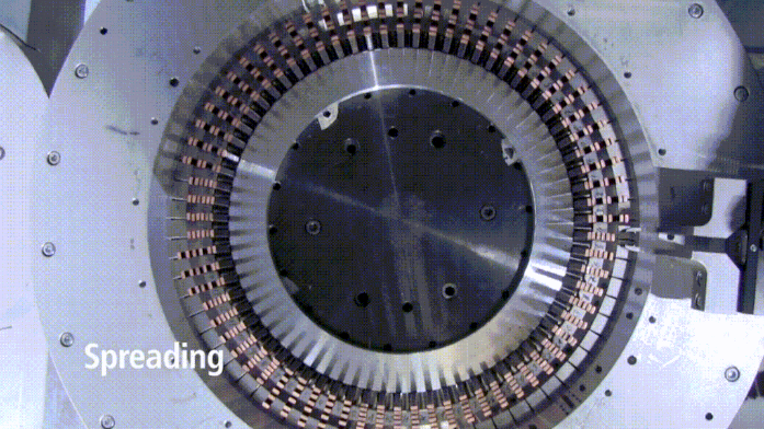
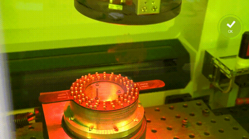
Insert the card coils into the profiling tooling, and then firmly insert all the hairpin coils into the iron core, and press them into the corresponding design size.In this part of the process, cross-layer automatic insertion has been upgraded from the previous 2-layer and 4-layer technology to the latest 6-layer and 8-layer technology. Some domestic enterprises have also completed the manufacture of this product.4. Flaring, twisting, weldingMove the fixture positioning mechanism equipped with the stator to the flaring station to be layered, and the flaring mechanism covers the upper ends of the flat wires of all layers except the innermost two layers, and pulls the flat wires to move outward to complete all layers of flat wires one after another. flaring.Move the twisting mechanism and the stator to the working position, and the flaring mechanism extends against the ends of the innermost two layers of flat wires, so that the ends of the innermost two layers of flat wires are aligned with the twisting mechanism, and then the flaring mechanism moves from the upper end of the flat wire. Walk and shrink back, then insert the ends of the two innermost layers of flat wires into the twisting mechanism, the inner and outer molds of the twisting mechanism rotate in opposite directions, complete the twisting process of the innermost two layers of flat wires, and complete all the flat wires again. Turn your head.Welding process (the picture comes from the official account of TRUMPF Laser)The existing welding methods mainly include laser welding or argon arc welding, both of which are formed by melting copper at an instantaneous high temperature to form solder joints, thereby realizing the electrical connection of the windings. At the same time, there are other companies that use CMT cold welding or other welding methods.The existing laser welding or argon arc welding technology has two main disadvantages:First, laser welding and argon arc welding need to generate high temperature instantaneously to melt copper, which is easy to damage the enameled wire paint film around the welding point and reduce the insulation reliability;Second, the number of hairpin coils or unilateral coils constituting the stator winding of the flat wire motor is large, which requires a large number of solder joints. Laser welding or argon arc welding generally weld the solder joints one by one, which seriously affects the production efficiency of the flat wire stator.
5. Coating and dipping
The detailed process of this process is as follows:
|
|
|
|
|
|
|
|
|
|
|
|
|
Before armature paint dripping
|
|
|
|
|
|
|
|
|
|
|
|
Before armature paint dripping
|
|
|
|
|
|
|
|
|
|
|
|
|
|
|
|
|
|
|
|
|
|
|
|
After armature dripping paint
|
|
|
|
|
There are currently two main types of coating materials: powder and liquid; the dipping process mainly includes traditional dipping, vacuum dipping, vacuum pressure dipping, drip dipping, etc., as well as EUV dipping process.For a long time, motor thermal management has been the main challenge faced by many car companies. The increasing cruising range and power density have put forward higher heat dissipation requirements for the motor. At present, the motor has been relying on the cooling system to achieve thermal management.At present, the motor manufacturing mainly adopts the dipping process, but there are problems such as poor heat dissipation performance, easy damage, and intolerant of organic oil. In this case, the vacuum potting process came into being.For vacuum potting, the required potting resin needs to have the following characteristics:
-
It should have good fluidity before curing. It can penetrate into the uneven gap on the surface of the winding. After potting, the outer surface of the workpiece should be smooth and flat, so that the rotating part of the motor has basically the same moment of inertia when rotating, reducing the sudden change of the motor speed and steering due to mechanical stress. The vibration caused by thermal changes reduces the resistance of the cooling medium to the rotating part of the motor.
-
It should have strong adhesion to the motor winding, strong cold and thermal shock toughness and sufficiently high mechanical strength.
-
It should have a high thermal conductivity to reduce the temperature difference between the inner and outer surfaces of the potting compound. On the one hand, it can quickly conduct the heat generated by the motor windings to the outer surface of the workpiece. On the other hand, the internal stress due to the temperature difference can be reduced.
-
It has good electrical insulation performance and oil resistance. After potting, the motor stator forms a whole, the heat dissipation and stator modal stiffness and damping performance are improved, the temperature rise and vibration noise are reduced, and the moisture resistance, shock resistance and corona resistance are improved. raised.


 XINDA
XINDA