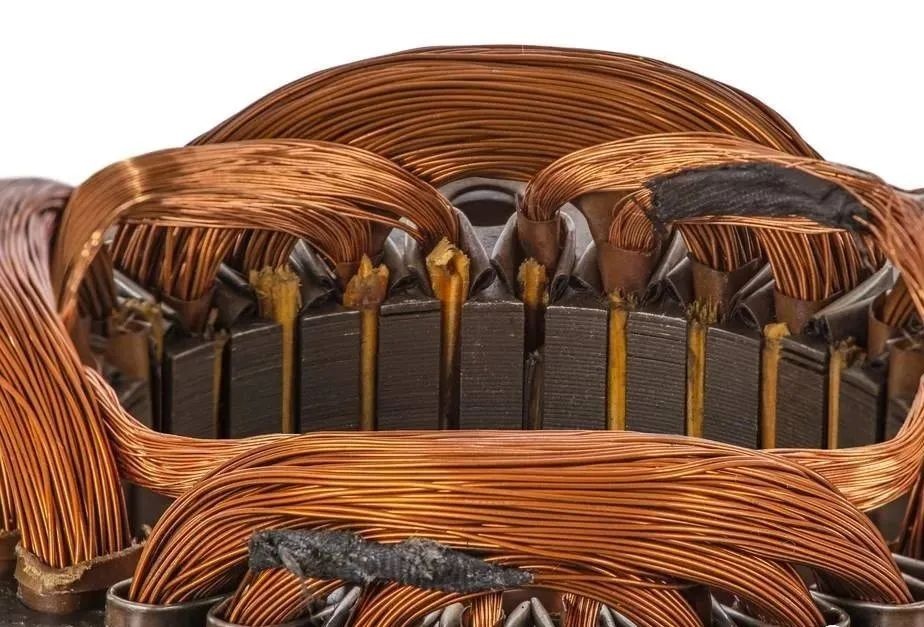
Although the phenomenon that the frequency converter damages the motor has attracted more and more attention, people still do not know the mechanism of this phenomenon, let alone how to prevent it. 1. The damage of the inverter to the motor The damage of the inverter to the motor includes two aspects, the damage of the stator winding and the damage of the bearing. This kind of damage generally occurs within a few weeks to ten months, and the specific time is related to the brand of the inverter, the brand of the motor, the power of the motor, the carrier frequency of the inverter, the length of the cable between the inverter and the motor, the ambient temperature, etc. Many factors are involved. The early accidental damage of the motor brings huge economic losses to the production of the enterprise. This loss is not only the cost of motor repair and replacement, but also the economic loss caused by unexpected shutdown. Therefore, when using the inverter to drive the motor, enough attention must be paid to the problem of motor damage. 2. The difference between inverter drive and power frequency drive To understand the mechanism that the power frequency motor is more easily damaged under the drive condition of the inverter, first understand the difference between the voltage of the inverter driven motor and the power frequency voltage. Then see how this difference can adversely affect the motor. The basic structure of the frequency converter includes two parts: rectifier circuit and inverter circuit. The rectifier circuit is a DC voltage output circuit composed of ordinary diodes and filter capacitors, and the inverter circuit converts the DC voltage into a pulse width modulated voltage waveform (PWM voltage). Therefore, the voltage waveform of the inverter-driven motor is a pulse waveform with varying pulse widths, not a sine wave voltage waveform. Driving the motor with pulse voltage is the root cause of easy damage to the motor. 3. The mechanism of inverter damage to motor stator winding When the pulse voltage is transmitted on the cable, if the impedance of the cable does not match the impedance of the load, reflection will occur at the load end. The result of the reflection is that the incident wave and the reflected wave are superimposed to form a higher voltage, and its amplitude can reach 2 times of the DC bus voltage at most, which is about 3 times of the input voltage of the inverter. Excessive peak voltage is applied to the coil of the motor stator, causing a voltage shock to the coil, and frequent overvoltage shocks will cause the motor to fail prematurely. After a motor driven by a frequency converter is impacted by a peak voltage, its actual life is related to many factors, including temperature, pollution, vibration, voltage, carrier frequency, and the process of coil insulation. The higher the carrier frequency of the inverter, the closer the output current waveform is to a sine wave, which will reduce the operating temperature of the motor and thus prolong the life of the insulation. However, a higher carrier frequency means a higher number of voltage spikes per second and a higher number of shocks to the motor. Figure 4 shows insulation life as a function of cable length versus carrier frequency. For a 200-foot cable, when the carrier frequency is increased from 3 kHz to 12 kHz (a 4-fold change), the insulation life decreases from about 80,000 hours to 2 10,000 hours (a difference of 4 times). The higher the temperature of the motor, the shorter the life of the insulation, when the temperature rises to 75°C, the life of the motor is only 50%. For a motor driven by an inverter, since the PWM voltage contains more high-frequency components, the motor temperature will be much higher than that of the power frequency voltage drive. 4. The mechanism of inverter damage to motor bearing The reason why the inverter damages the motor bearing is that there is a current flowing through the bearing, and this current is in a state of intermittent connection. The intermittently connected circuit will generate an arc, and the arc burns the bearing. There are two main reasons for the current flowing in the bearing of the AC motor. First, the induced voltage caused by the imbalance of the internal electromagnetic field, and second, the high-frequency current path caused by the stray capacitance. The magnetic field inside an ideal AC induction motor is symmetrical. When the currents of the three-phase windings are equal and the phases differ by 120, no voltage will be induced on the shaft of the motor. When the PWM voltage output by the inverter causes the magnetic field inside the motor to be asymmetric, a voltage will be induced on the shaft, and the voltage amplitude is 10~30V, which is related to the driving voltage. The higher the driving voltage, the higher the voltage on the shaft. high. When the value of this voltage exceeds the dielectric strength of the lubricating oil in the bearing, a current path is formed. During the rotation of the shaft, at some point, the insulation of the lubricating oil blocks the current again. This process is similar to the on-off process of a mechanical switch, in which arcs are generated, ablating the surfaces of the shaft, balls, and bowls, forming pits. If there is no external vibration, the small pit will not have an excessive effect, but if there is external vibration, a groove will be generated, which has a great impact on the operation of the motor. In addition, experiments show that the voltage on the shaft is also related to the fundamental frequency of the output voltage of the inverter. The lower the fundamental frequency, the higher the voltage on the shaft and the more serious the bearing damage. In the early stage of motor operation, when the lubricating oil temperature is low, the current amplitude is 5-200mA, such a small current will not cause any damage to the bearing. However, when the motor runs for a period of time, as the temperature of the lubricating oil increases, the peak current will reach 5-10A, which will cause arcing, forming small pits on the surface of the bearing components. 5. Protection of motor stator windings When the length of the cable exceeds 30 meters, modern inverters will inevitably generate peak voltages at the motor end, shortening the life of the motor. There are two ideas to prevent damage to the motor. One is to use a motor with higher electrical resistance of the winding insulation (generally called a variable frequency motor), and the other is to take measures to reduce the peak voltage. The former measure is suitable for newly built projects, and the latter measure is suitable for retrofitting existing motors. At present, there are four commonly used motor protection methods: 1) Install a reactor at the output end of the inverter: This measure is the most commonly used, but it should be noted that this method has a certain effect on shorter cables (below 30 meters), but sometimes the effect is not ideal. 2) Install a dv/dt filter at the output end of the inverter: This measure is suitable for occasions where the cable length is less than 300 meters. The price is slightly higher than that of the reactor, but the effect has been significantly improved. 3) Install a sine wave filter at the output end of the inverter: This measure is ideal. Because here, the PWM pulse voltage is turned into a sine wave voltage, and the motor works under the same conditions as the power frequency voltage, and the problem of peak voltage has been completely solved (no matter how long the cable is, there will be no peak voltage) . 4) Install a peak voltage absorber at the interface between the cable and the motor: The disadvantage of the previous measures is that when the power of the motor is large, the volume and weight of the reactor or filter are large, and the price is high. In addition, the reactor And the filter will lead to a certain voltage drop, affecting the output torque of the motor, the use of inverter peak voltage absorber can overcome these shortcomings.


 XINDA
XINDA