








What is the principle and structure of a speed reducer?
What is the principle and structure of a speed reducer?
A speed reducer is an important mechanical device. As a transmission device, it plays a vital role in many industrial applications. It is commonly used as a speed reduction transmission device between the prime mover and the driven machine. Its main function is to reduce speed while increasing torque.
01
Working principle
A speed reducer primarily relies on a gear with fewer teeth on the input shaft meshing with a larger gear with more teeth on the output shaft to achieve speed reduction. Its transmission ratio is equal to the ratio of the input speed to the output speed, and also equal to the ratio of the number of teeth on the driven gear to the number of teeth on the driving gear.
Its basic structure includes transmission components (gears or worm gears), shafts, bearings, a housing, and reducer accessories. The combination of gears, shafts, and bearings, which integrates the pinion and shaft, can be called a gear shaft. The housing, as a major component of the reducer, needs to bear the pressure of all parts and therefore must possess a certain level of strength and rigidity.
02
Classified by transmission type
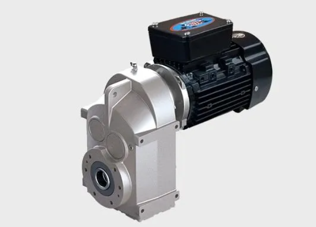
Gear reducer
Features: High transmission efficiency, strong load-bearing capacity, compact structure, smooth transmission, and long service life.
It mainly relies on the meshing of gears with different numbers of teeth to achieve speed reduction. The high-speed rotation of the motor is transmitted to the pinion through the input shaft, and the pinion then drives the meshing large gear to rotate. Since the large gear has more teeth than the pinion, the speed is reduced and the torque is increased.
Structural composition:
Enclosure : Provides support and protection, houses internal components, and ensures good lubrication and sealing.
Gear set : including driving gear (small gear) and driven gear (large gear), is the core component for achieving speed reduction.
Shaft : Used to support and fix gears and transmit torque.
Bearings: Reduce friction and wear on the shaft during rotation, ensuring smooth shaft operation.
Lubrication and sealing system: Ensures that gears and bearings are adequately lubricated and prevents lubricant leakage and impurities from entering.
Gear reducers are widely used in various equipment in industrial production, such as hoisting machinery, metallurgical equipment, mining machinery, chemical equipment, and food machinery.
worm gear reducer
Features: Large transmission ratio, compact structure, and smooth transmission.
It primarily relies on the meshing transmission between the worm gear and the worm to achieve speed reduction. The worm is similar to a screw, with a large lead angle, while the worm gear is a specially shaped gear. When the worm rotates, the interaction between the helical teeth of the worm and the teeth of the worm gear transmits power to the worm gear, thereby achieving speed reduction.
Structurally, a worm gear reducer typically includes components such as a housing, worm, worm wheel, shaft, bearings, and oil seals. The housing provides support and protection; the worm and worm wheel are key components for achieving speed reduction; the shaft supports the worm and worm wheel and transmits torque; bearings reduce friction and wear; and oil seals provide a seal to prevent lubricating oil leakage and the ingress of external impurities.
Worm gear reducers are widely used in various mechanical transmission systems, such as lifting equipment, mining machinery, and construction machinery. They are especially suitable for applications requiring a large transmission ratio, limited space, and a certain degree of stability.
Planetary gear reducer
Features: Compact structure, small size, and light weight; high load-bearing capacity, capable of transmitting large power; high transmission efficiency; high precision, smooth operation, and low noise.
It employs the principle of planetary gear transmission and consists of a sun gear, multiple planet gears, an internal gear ring, and a planet carrier. Power is input from the sun gear, and the planet gears revolve around the sun gear while rotating on their own axes, outputting power through the planet carrier. Because multiple planet gears share the load, it can withstand a large torque.
Compared to other types of speed reducers, planetary gear reducers have a wider transmission ratio range and can achieve multi-stage reduction. Due to their compact structure and high efficiency, they can provide a large reduction ratio and output torque within a limited space. They also have good adaptability and can be used in a variety of working conditions and fields.
Planetary gear reducers are widely used in various mechanical transmission systems, such as industrial robots, CNC machine tools, automated production lines, aerospace, and medical devices, where high precision, load-bearing capacity, and transmission efficiency are required.
03
Classified by gear shape
● Cylindrical gear reducer
● Bevel gear reducer
● Bevel-cylindrical gear reducer
04
Classification according to the arrangement of transmission
● Deployable speed reducer
● Flow divider type speed reducer
● Coaxial reducer
Different types of speed reducers, such as gear reducers, worm gear reducers, and planetary reducers, have different structures and working principles, but they are all based on the fundamental principles and structural components mentioned above. In practical applications, selecting a suitable speed reducer requires considering multiple factors, such as transmission ratio, output torque, speed, efficiency, accuracy, and reliability. Furthermore, selection and design must be based on specific working conditions and requirements to ensure the speed reducer operates normally and meets usage requirements.
 XINDA