B L O G
XINDA MOTOR
  1. Home
  2. Knowhow

A closer look at the key technical requirements of motor manufacturing

Date:2026-04-12   Author:Shandong Xinda Motor Co., Ltd.

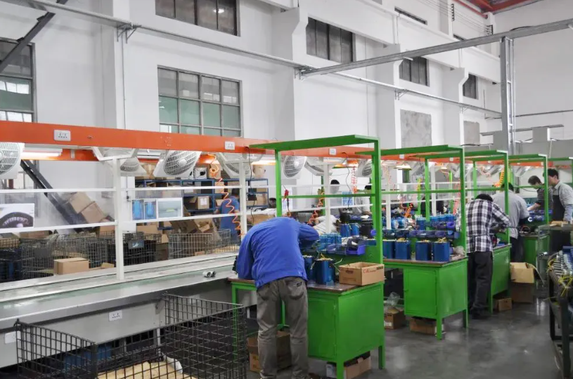
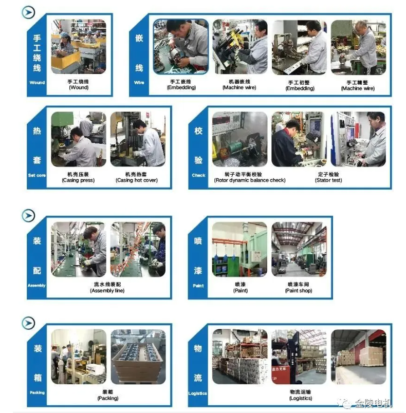
The technical and economic indicators of an electric motor are largely related to its manufacturing materials and processes. In electric motor production, products with the same design structure and from the same batch of raw materials can often vary significantly in quality. Without advanced manufacturing technologies, it is difficult to produce high-quality products. Today, let's look at some of the key processes in electric motor manufacturing.


01

Base


a. The dimensional tolerances and surface roughness of each machined part shall conform to the specifications in the drawings. 
b. The form and position tolerances of each machined surface shall conform to the specifications in the drawings. Among them, the coaxiality of the end stops and the inner circle, and the runout of the end faces to the centerline of the end stops are key to the machining of the machine base. The fit between the inner circle and the iron core shall have appropriate tightness to ensure that the stator iron core does not loosen or move during the operation of the motor. 
c. For motors with feet, the foot plane should be parallel to the shaft centerline. The distance between the foot holes and the centerline of the motor base should be symmetrical and meet the specified tolerances.

02

End cap


The rigidity of the end cover structure, the dimensional accuracy of the stop and bearing housing, and the form and position deviations will affect the uniformity of the air gap between the stator and rotor. These factors should be considered during design and manufacturing.
a. Dimensional tolerances, cylindricity, and surface roughness of the bearing housing.
b. Dimensional tolerances, cylindricity, and roughness of the stop. 
c. Coaxiality of the bearing housing and the stop. 
d. The jump of the end face to the center line of the stop. 
e. Depth from the end face of the stop to the bearing housing. The end cover wall thickness should generally not be less than 5mm, the end cover stop should be chamfered, and the machining allowance should be more than 3mm.

03

motor shaft


Spindles are typically made of 45 high-quality carbon structural steel or 40Cr alloy steel. Spindle machining is divided into two stages: pre-machining and forming machining. Pre-machining includes straightening the round steel, blanking, end face finishing, and drilling the center hole. Forming machining includes rough turning, semi-finish turning, grinding the outer diameter, and milling keyways.

The diameter and surface roughness of the shaft core, bearing bearings, rotor core outer diameter and surface roughness, bearing spacing at both ends, and coaxiality of the core outer circle with the shaft are all critical machining parameters. The shaft, core, and fan blades should have appropriate tightness to ensure that the rotor core and fan blades do not loosen or move during motor operation. Furthermore, the dimensional tolerances of the shaft extension and keyway should conform to the relevant product standards for installation dimensional tolerances.

04

stator core


The requirements for lamination are as follows:

a. The stamped parts should meet the dimensional tolerances specified in the drawings. 
b. The surface of the laminations should be smooth and of uniform thickness. Burrs on stator and rotor laminations should be ≤0.05mm. 
c. Coaxiality of the inner circle or center hole and the outer circle of the stamping: Φ0.04 ~ 0.06mm for one stamping of the inner and outer circles, and appropriately relaxed for two stampings of the inner and outer circles. 
d. Non-uniformity of the tooth distribution in the lamination, i.e., the difference between the maximum and minimum tooth width is grade 3 or 4. 
e. The center line of the groove should pass through the center of the circle and should not have obvious skewness. 
f. The insulating layer on the surface of the lamination should be thin and uniform, and have sufficient dielectric, oil resistance and moisture resistance.
g. The number of blanking pieces with missing edges shall not exceed 2%, and the height of the missing edge shall not exceed 20% of the height of the magnetic yoke.

The requirements for lamination stacking are as follows:
The task of core pressing is to arrange and press a certain number of laminations together to form a whole that is accurate in size, neat in shape, and tightly fitted.

a. The core weight or stacking factor must conform to the specifications in the drawings. Insufficient core weight will increase the magnetic induction intensity, leading to increased iron losses in the motor, increased excitation current, and reduced power factor and efficiency.
b. The pressure should be uniform, and the tightness should be appropriate. Under the combined effects of mechanical vibration, electromagnetic forces, and heat, the iron core should not loosen or deform. If the iron core is too loose, the number of laminations within a certain length will decrease, resulting in insufficient magnetic cross-section, vibration noise, and damage to insulation. If the pressure is too tight, the insulation resistance between laminations will decrease, or even damage the inter-lamination insulation, leading to a significant increase in iron loss. Uneven pressure, with excessive tightness, easily damages the insulation, while excessive looseness often causes the iron core to loosen.
c. Geometric dimensions should be accurate. The total length of the core, the dimensions of the slots, and the dimensions and positions of the radial ventilation slots should all meet the specified requirements. The outer diameter tolerance of the core should ensure the process requirements for the coaxiality of the externally press-fitted stator core. 
d. Shape requirements. The coaxiality of the core should be within the specified range, and the laminations should not exhibit a wavy shape after pressing. The edges of the core, especially the teeth, should not be raised. 
e. The position of the axial centerline of the core should meet the specified requirements to ensure the central symmetry of the stator and rotor. 
f. The insulation between core laminations should not be damaged.

05

Rotor


Surface quality requirements:
a. The end ring, fan blades, and balance column must be free of cracks. 
b. The size and depth of the shrinkage cavity on the end ring surface should be less than 20% of the end ring height, with a maximum of 3mm, and only one such cavity is allowed on each end. 
c. Damage to the blades and sharp corners should be less than 3mm. 

Size requirements:
a. Rotor core length tolerance.
      Core length L < 160mm, allowable tolerance +2.0mm;
      The core length L ≥ 160mm, with an allowable tolerance of +2.5mm. 
b. Runout of the outer circle of the end ring and the outer circle of the iron core.
      The outer diameter of the iron core Φ is less than 100mm, and the maximum runout is no more than 1.0mm;
      The outer diameter of the iron core is Φ < 250mm, and the maximum runout is no more than 2.0mm;
      The outer diameter of the iron core is Φ250~400mm, and the maximum runout is no more than 3.0mm;
      The outer diameter of the iron core is Φ > 400mm, and the maximum runout is no more than 4.0mm. 
c. The end ring deflects off the core end face: same as b. 
d. The allowable deviation of rotor slot skew is ±1.0mm. 
e. The oblique groove line on the outer circular surface of the rotor must be straight, and the rotor misalignment should generally be less than 0.5mm when viewed from the oblique groove line.

Internal quality requirements:
Check for defects such as broken strips, cracks, pores, looseness, and shrinkage cavities.

06

winding


The winding is a critical component of an electric motor, and also its most vulnerable and easily damaged part, affected by electromagnetic, thermal, mechanical vibration, and environmental factors. The lifespan and operational reliability of an electric motor mainly depend on its winding.

Coil manufacturing technology requirements:

a. The diameter and number of turns of the winding wire should be accurate. Each coil should have no more than one joint, each phase coil should have no more than two joints, and each unit should have no more than four joints. Joints must be made at the beveled edge of the end, and the wrapping should comply with regulations.
b. The dimensions are appropriate and meet the requirements, guaranteed by the winding die. 
c. The coils should be arranged neatly, without crossing or damaging the insulation. The insulation between turns and to ground of multi-turn coils should be good and reliable.

Winding insertion, shaping, and wiring technical requirements:

a. Before winding, the core should be inspected and cleaned. Any protrusions on the stator surface and in the slots should be filed flat and blown clean (not in the winding area). 
b. The winding pitch (slot pitch), the connection between coils, and the relative positions of the leads must be correct. 
c. The winding slot insulation, layer insulation, and phase-to-phase insulation should be in good and reliable condition. The quality of the insulation materials and the structural dimensions should meet the requirements. 
d. The surface of the slot wedge should be flat and smooth. It should not damage the winding insulation during insertion, should have appropriate tightness, and its ends should not be cracked. It should not protrude beyond the inner circumference of the core. The lengths of the winding, insulation, and slot wedge protruding from both ends of the stator core should be symmetrical. 
e. The conductors at the winding ends should be neatly arranged without serious crossing. The end binding and insulation should meet the requirements. 
f. When winding and shaping, metal tools must not be used to directly contact the winding, and excessive force must not be applied to avoid damaging the insulation. 
g. Lead wire joints should be securely welded to ensure good contact, sufficient mechanical strength, and a smooth surface, without any detachment or incomplete soldering. Strict measures should be taken to prevent copper dust, solder slag, and other spatter from damaging the winding insulation and from entering the winding. 
h. Lead-out wires should be arranged neatly, of the same length, and meet the requirements. Those requiring markings should be placed in the same designated location. 
i. End dimensions should conform to the drawings or tooling requirements. 
j. The insulation at the bottom of the slot should not be cracked, and the conductors should not have damaged insulation. If there is a crack at the slot opening, it must be padded with the same material as the slot insulation, but the total number of cracks should not exceed 3, and the cracks should not extend to the core. 
k. Winded stator cores are not allowed to roll on the ground, and the coil insulation must not be damaged during stacking and handling.

Winding impregnation and drying technical requirements:

Impregnation is a common treatment for the insulation of windings in small and medium-sized electric motors. The impregnation process is as follows: 1. Pre-baking; 2. Impregnation; 3. Drying after dripping varnish. Sometimes, the windings need to be impregnated multiple times depending on the requirements.
a. The process parameters and insulation resistance of pre-baking, impregnation, and drying should meet the specified requirements. 
b. The impregnating varnish should be uniform and transparent, free of impurities, lumps, and deterioration. The viscosity of the varnish should meet the process requirements.
c. After drying, the color of the varnish film on the winding surface should be uniform and consistent. The varnish film should not be sticky to the touch and should be slightly elastic. There should be no cracks or wrinkles on the surface, no deformation at the ends, and no bumps, exposed copper, separation of lead wires, or misalignment of slot wedges.

07

Process Flow