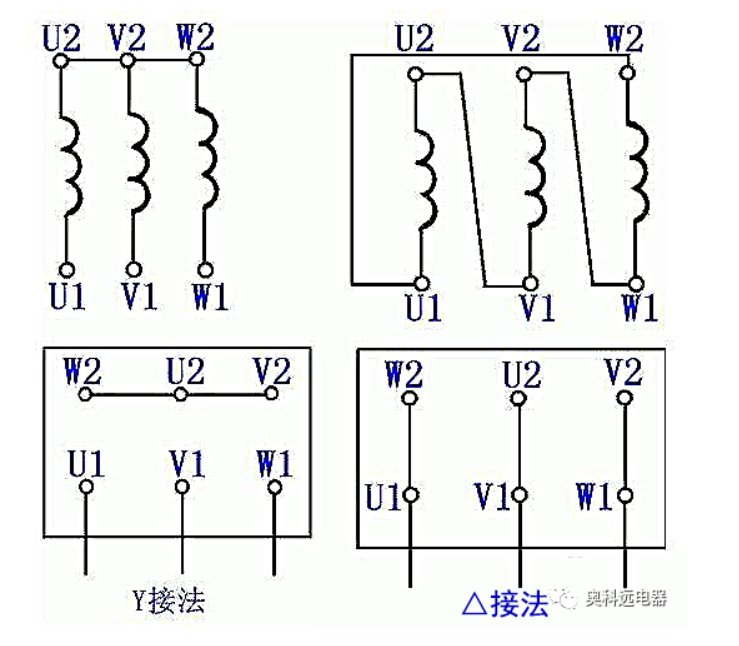
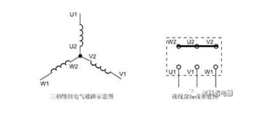
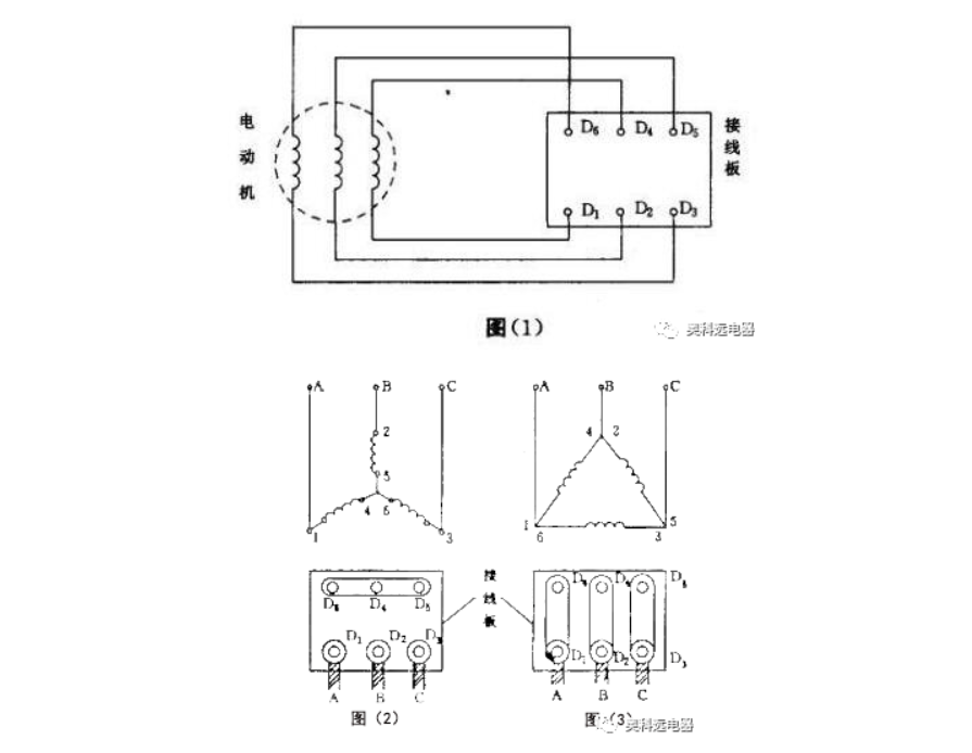
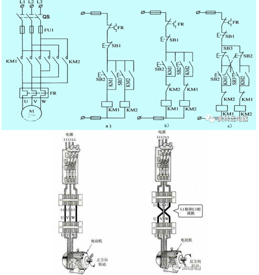
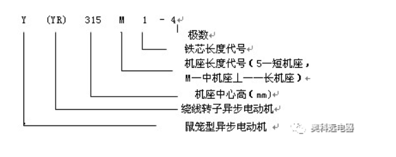
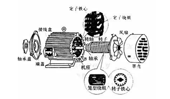
1. Introduction of three-phase motor A three-phase motor means that when the three-phase stator winding of the motor (each phase differs by 120 degrees electrical angle) is supplied with three-phase alternating current, a rotating magnetic field will be generated. This rotating magnetic field cuts the rotor winding, thereby generating an induced current in the rotor winding (the rotor winding is a closed path). The current-carrying rotor conductor will generate an electromagnetic force under the action of the stator rotating magnetic field, thereby forming an electromagnetic torque on the motor shaft, driving the motor to rotate, and the direction of motor rotation is the same as the direction of the rotating magnetic field. Working principle: When symmetrical three-phase alternating current is passed into the three-phase stator winding, a rotating magnetic field is generated that rotates clockwise along the inner circle space of the stator and rotor at a synchronous speed n1. Since the rotating magnetic field rotates at a speed of n1, the rotor conductor is stationary at the beginning, so the rotor conductor will cut the stator rotating magnetic field and generate an induced electromotive force (the direction of the induced electromotive force is determined by the right-hand rule). Since the two ends of the rotor conductor are short-circuited by the short-circuit ring, under the action of the induced electromotive force, an induced current will be generated in the rotor conductor with a direction basically consistent with the induced electromotive force. The current-carrying conductor of the rotor is acted upon by an electromagnetic force in the stator magnetic field (the direction of the force is determined by the left-hand rule). The electromagnetic force generates an electromagnetic torque on the rotor shaft, driving the rotor to rotate along the direction of the rotating magnetic field. Through the above analysis, we can conclude that the working principle of the motor is as follows: when the three-phase stator winding of the motor (each phase differs by 120 degrees electrical angle) is supplied with three-phase symmetrical alternating current, a rotating magnetic field will be generated. This rotating magnetic field cuts the rotor winding, thereby generating an induced current in the rotor winding (the rotor winding is a closed path). The current-carrying rotor conductor will generate an electromagnetic force under the action of the stator rotating magnetic field, thereby forming an electromagnetic torque on the motor shaft, driving the motor to rotate, and the direction of motor rotation is the same as the direction of the rotating magnetic field. 2. Three-phase motor wiring 3. Practical Operation 1. Star connection: In fact, it is to connect all the ends of the click coils together. Just connect U2, v2, and w2 together. 2. Triangle connection That is, the ends are connected, u2 connects to w1, w2 connects to v1, v2 connects to u 4. The difference between triangle and star connection The voltage across the coil of the motor in star connection is 220V. (Low voltage reduces starting current) The voltage across the coil of the motor in delta connection is 380V. 5. Actual Cases Each phase of the three-phase stator winding of a three-phase asynchronous motor has two lead wire ends. One end is called the head end and the other end is called the tail end. It is stipulated that the head end of the first phase winding is represented by D1 and the tail end is represented by D4; the head end of the second phase winding is represented by D2 and the tail end is represented by D5; the head end and the tail end of the third phase winding are represented by D3 and D6 respectively. These six lead wire ends are connected to the terminal of the terminal box, and the terminal is marked with D1 to D6 accordingly, as shown in Figure (1). The six terminals of the three-phase stator winding can be connected into a star or triangle. The star connection method is to connect the ends of the three-phase winding in parallel, that is, connect the three terminals D4, D5, and D6 together with copper sheets, and connect the first ends of the three-phase winding to the three-phase AC power supply, that is, connect D1, D2, and D3 to the A, B, and C phase power supplies respectively, as shown in Figure (2). The triangle connection method is to connect the first end D1 of the first phase winding to the end D6 of the third phase winding, and then connect to the first phase power supply; the first end D2 of the second phase winding to the end D4 of the first phase winding, and then connect to the second phase power supply; the first end D3 of the third phase winding to the end D5 of the second phase winding, and then connect to the third phase power supply. That is, on the terminal board, connect the terminals D1 and D6, D2 and D4, and D3 and D5 with copper sheets, and then connect to the three-phase power supply respectively, as shown in Figure (3). Special circumstances: If you want to reverse the three-phase stator winding, you can reverse the head and end of the three-phase winding together, for example, reverse the ends D4, D5, and D6 of the three-phase winding as the head, and use D1, D2, and D3 as the end, but never reverse the head and end of one phase winding alone, otherwise it will cause wiring errors. If a wiring error occurs in the junction box, or the head and end of the winding are wrong, the motor may not start normally, and the starting current will be too large due to long-term power-on, causing serious heating of the motor and shortening its life. In severe cases, the motor winding will be burned or the power supply will be short-circuited. 6. Forward and reverse control of three-phase asynchronous motor Main electrical components: 3 push button switches, 2 contactors, 1 thermal overload. It is best to add 3 fuses to protect the 3 live wires. To achieve forward and reverse control of the motor, any two phases in the phase sequence of its power supply can be swapped (we call it phase change). Usually, the V phase remains unchanged, and the U phase is swapped with the W phase. In order to ensure that the phase sequence of the motor can be reliably swapped when the two contactors are in action, the upper port wiring of the contactor should be kept consistent during wiring, and the phase is switched at the lower port of the contactor. Since the phase sequence of the two phases is swapped, it is necessary to ensure that the two KM coils cannot be energized at the same time, otherwise a serious phase-to-phase short circuit fault will occur, so interlocking must be adopted. Forward start processPress the start button SB2, the contactor KM1 coil is energized, and the auxiliary normally open contact of KM1 connected in parallel with SB2 is closed to ensure that the KMl coil is continuously energized, the main contact of KM1 connected in series in the motor circuit is continuously closed, and the motor continues to run in the forward direction. Stop process Press the stop button SB1, the contactor KM1 coil is de-energized, and the auxiliary contacts of KM1 connected in parallel with SB2 are disconnected to ensure that the KM1 coil is continuously de-energized. The main contacts of KM1 connected in series in the motor circuit are continuously disconnected, cutting off the power supply to the motor stator and stopping the motor. Reverse startup process Press the start button SB3, the contactor KM2 coil is energized, and the auxiliary normally open contact of KM2 connected in parallel with SB3 is closed to ensure that the KM2 coil is continuously energized. The main contact of KM2 connected in series in the motor circuit is continuously closed, and the motor continuously runs in the reverse direction. 7. Three-phase motor modelTYPE: Type (model). TYPE: Chinese means form, style, type, variety; it is represented as model in motors. The product model consists of four parts: product code, specification code, special environment code and supplementary code. Their arrangement order is: product code - specification code - special environment code - supplementary code. Product code: It consists of four sections in sequence: motor type code, motor feature code, design serial number and excitation method code. 1. The type code is the Chinese phonetic letter used to characterize the various types of motors. Additional information:Take the 7.5KW motor Y132M-4 as an example, Y means Y series three-phase asynchronous motor, 132 means the motor center height is 132MM, M means medium base, and 4 means four-pole motor. Take the YH100L1-4 motor as an example, YH means YH series high-slip three-phase asynchronous motor, 100 means the motor center height is 100MM, L means long base, 1 means the iron core length code, and 4 means four-pole motor. There are many types of motors, so there are different motor models, including YD variable speed, YEJ braking, YVP variable frequency and other three-phase heterodyne frequency motors. The motor frame number: generally refers to the height of the motor center. The M, L, S in the motor model refers to the length of the housing. 1 and 2 refer to the length of the iron core. Shangyu Dongxing specializes in speed reducers and motors. You can ask any other questions. 8. Meaning of model lettersJ——asynchronous motor; O——enclosed; L——aluminum wire winding group; W——outdoor; Z——metallurgical lifting; Q——high starting wheel; D——multi-speed; B——explosion-proof; R——winding type; S——double squirrel cage; K——high speed; H——high slip rate. 9. Three-phase motor compositionThe three-phase asynchronous motor consists of two basic parts: a fixed stator and a rotating rotor. The rotor is installed in the inner cavity of the stator and supported on two end covers by bearings. In order to ensure that the rotor can rotate freely in the stator, there must be a gap between the stator and the rotor, called the air gap. The air gap of the motor is a very important parameter, and its size and symmetry have a great influence on the performance of the motor. Figure 2 shows the components of a three-phase cage asynchronous motor. 10. Speed regulation methodVariable pole speed regulation This speed regulation method changes the stator winding connection mode to change the number of stator poles of the cage motor to achieve the purpose of speed regulation. The characteristics are as follows: 1. It has hard mechanical properties and good stability; 2. No slip loss, high efficiency; 3. Simple wiring, convenient control and low price; 4. Step speed regulation, the step difference is large, and smooth speed regulation cannot be achieved; 5. It can be used in conjunction with voltage and speed regulation and electromagnetic slip clutch to obtain smooth speed regulation characteristics with higher efficiency. This method is suitable for production machinery that does not require stepless speed regulation, such as metal cutting machine tools, elevators, lifting equipment, fans, water pumps, etc. Frequency Variable frequency speed regulation is a speed regulation method that changes the frequency of the motor stator power supply, thereby changing its synchronous speed. The main equipment of the variable frequency speed regulation system is the frequency converter that provides variable frequency power supply. Frequency converters can be divided into two categories: AC-DC-AC frequency converters and AC-AC frequency converters. Most domestic frequency converters use AC-DC-AC frequency converters. Its characteristics: 1. High efficiency, no additional loss during speed regulation; 2. Wide range of applications, can be used for cage-type asynchronous motors; 3. Large speed regulation range, hard characteristics, high precision; 4. Complex technology, high cost, difficult maintenance and repair. This method is suitable for occasions requiring high precision and good speed regulation performance. Cascade speed regulation Cascade speed regulation refers to the process of inserting an adjustable additional potential in series into the rotor circuit of a wound-rotor motor to change the motor's slip and achieve the purpose of speed regulation. Most of the slip power is absorbed by the additional potential, and then used to generate additional devices to return the absorbed slip power to the grid or convert it into energy for use. According to the way the slip power is absorbed and utilized, cascade speed regulation can be divided into motor cascade speed regulation, mechanical cascade speed regulation and thyristor cascade speed regulation. Thyristor cascade speed regulation is mostly used, and its characteristics are: 1. The slip loss during the speed regulation process can be fed back to the power grid or production machinery, with high efficiency; 2. The device capacity is proportional to the speed range, which saves investment and is suitable for production machinery with a speed range of 70%-90% of the rated speed; 3. When the speed regulating device fails, it can switch to full speed operation to avoid production stoppage; 4. The power factor of thyristor cascade speed regulation is low and the harmonic influence is large. This method is suitable for fans, water pumps, rolling mills, mine hoists, and extruders. The rotor of the resistance-controlled winding asynchronous motor is connected in series with an additional resistor to increase the slip rate of the motor and run the motor at a lower speed. The larger the resistance connected in series, the lower the speed of the motor. This method has simple equipment and convenient control, but the slip power is consumed in the form of heat on the resistor. It is a step-by-step speed regulation with softer mechanical characteristics. Stator voltage and speed regulation method When the stator voltage of the motor is changed, a set of different mechanical characteristic curves can be obtained, thereby obtaining different speeds. Since the torque of the motor is proportional to the square of the voltage, the maximum torque drops a lot, and its speed regulation range is small, making it difficult to use general cage motors. In order to expand the speed regulation range, voltage and speed regulation should use cage motors with large rotor resistance values, such as torque motors specially designed for voltage and speed regulation, or connect frequency-sensitive resistors in series with wound-type motors. In order to expand the stable operating range, feedback control should be used when the speed regulation is above 2:1 to achieve the purpose of automatically adjusting the speed. The main device for voltage and speed regulation is a power supply that can provide voltage changes. Commonly used voltage regulation methods include series saturated reactors, autotransformers, and thyristor voltage regulation. Thyristor voltage regulation is the best. Characteristics of voltage and speed regulation: 1. The voltage and speed regulation circuit is simple and easy to realize automatic control; 2. During the voltage regulation process, the slip power is consumed in the rotor resistance in the form of heat, which is inefficient. 3. Voltage and speed regulation are generally suitable for production machinery below 100KW. Electromagnetic speed regulation The electromagnetic speed regulating motor consists of three parts: a cage motor, an electromagnetic slip clutch and a DC excitation power supply (controller). The DC excitation power supply has a small power and is usually composed of a single-phase half-wave or full-wave thyristor rectifier. Changing the conduction angle of the thyristor can change the magnitude of the excitation current. The electromagnetic slip clutch consists of three parts: the armature, the magnetic pole and the excitation winding. The armature has no mechanical connection with the latter and can rotate freely. The coaxial connection between the armature and the motor rotor is called the active part, which is driven by the motor; the magnetic pole is connected to the load shaft with a coupling and is called the driven part. When the armature and the magnetic poles are both stationary, if the excitation winding is passed with direct current, several pairs of magnetic poles with alternating N and S polarities will be formed along the circumferential surface of the air gap, and their magnetic flux passes through the armature. When the armature rotates with the traction motor, the armature induces eddy currents due to the relative motion between the armature and the magnetic poles. The interaction between the eddy currents and the magnetic flux generates torque, which drives the rotor with magnetic poles to rotate in the same direction, but its speed is always lower than the speed N1 of the armature. This is a slip speed regulation method. By changing the DC excitation current of the slip clutch, the output torque and speed of the clutch can be changed. Speed regulation characteristics of electromagnetic speed regulating motor: ·Simple device structure and control circuit, reliable operation, and easy maintenance; 1. Smooth and stepless speed regulation; 2. No harmonic impact on the power grid; 3. Large speed loss and low efficiency. This method is suitable for production machinery with medium and small power that requires smooth sliding and short-term low-speed operation. Coupler speed regulation A hydraulic coupling is a hydraulic transmission device, generally composed of a pump wheel and a turbine, which are collectively called working wheels and are placed in a sealed housing. A certain amount of working fluid is filled in the housing. When the pump wheel rotates under the drive of the prime mover, the liquid in it is pushed by the blades to rotate. When it enters the turbine along the outer ring of the pump wheel under the action of centrifugal force, it gives thrust to the turbine blades in the same direction, so that it drives the production machinery to operate. The power transmission capacity of the hydraulic coupling is consistent with the relative amount of liquid in the housing. During the working process, changing the filling rate can change the turbine speed of the coupling, and achieve stepless speed regulation. Its characteristics are: 1. The power adaptability range is wide, which can meet the needs of different powers from tens of kilowatts to thousands of kilowatts; 2. Simple structure, reliable operation, easy use and maintenance, and low cost; 3. Small size, large capacity; 4. Convenient control and adjustment, easy to achieve automatic control. This method is suitable for speed regulation of fans and water pumps.


 XINDA
XINDA