


Analysis of the motor servo control principle
Date:2024-06-13 Author:Shandong Xinda Motor Co., Ltd.
Servo control technology is necessary to determine the position of the motor. This chapter will introduce the principles of servo control. We will also introduce the application of programmable servo/sequence controller (PSC) in servo control.
We will explain motor servo control, first let's start with the basis of servo control "feedback control".
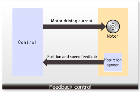
Feedback control
A motor is a device that converts electrical energy into rotational motion. In order to rotate the motor properly, feedback control must be performed. Feedback control will monitor how the motor rotates and determine the amount of current supplied to the motor based on the results. In other words, the appropriate speed can be maintained by the following steps: 1. Detect the motor speed. 2. Decide whether the motor speed should be increased or decreased. 3. Based on the decision, increase or decrease the current supplied to the motor.
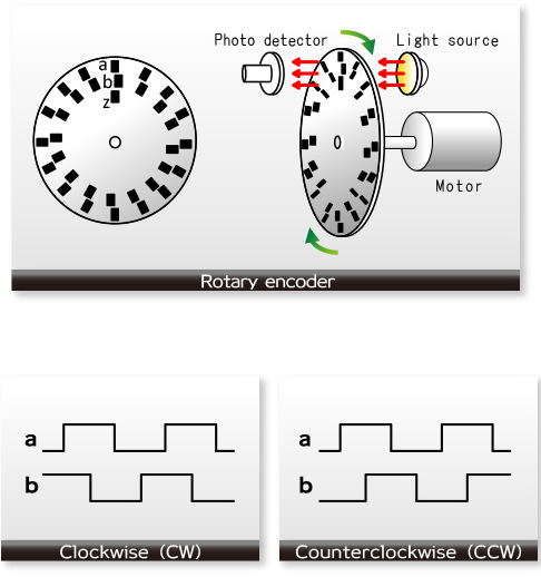
Rotary encoders
In order to perform feedback control, it is necessary to obtain information about the rotation of the rotor. One of the devices that obtains this information is a rotary encoder. The description of a rotary encoder is as follows.
A disk with many holes is placed on the rotor. A photodetector is placed on one side of the disk and a light source is placed on the other side. The disk rotates with the rotor. When the holes of the disk are in front of the light source, the light reaches the photodetector, and the holes of the disk are detected. If the rotor rotates slowly, the period of hole movement will become longer. If the rotor rotates quickly, the period of hole detection will become shorter. Thus, the rotation speed of the rotor can be detected. In addition, an extra hole is made on the disk, and it is used to determine the starting point of the disk. In this way, even if the holes appear one after another, the number of holes can be counted from the starting point. In this way, the current rotation position of the rotor can be detected. However, important information about the conversion is also lost. That is, it is impossible to obtain information about whether the rotor rotates clockwise or counterclockwise. So we make another row of holes so that each new hole is slightly offset from the original hole. In this way, it is possible to determine whether the rotor rotates clockwise (CW) or counterclockwise (CCW) based on the relative position relationship of the two rows of holes.
This is the working principle of a rotary encoder.
Servo control
Servo control is a type of feedback control that is often used for motor control.
Servo control is used in situations where there are two objects, an "instructor" and an "operator", where the "instructor" gives commands and the "operator" executes them. Servo control is a way to make the "operator" strictly follow the order. For example, when a teacher says "go", "stop", or "turn right" to a student, the student moves as instructed. This is servo control.
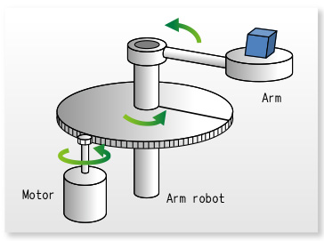
Let's look at servo control of a motor: how to move an arm robot. For example, suppose an arm is fixed to a large gear, which rotates with a small gear mounted on a motor. The rotation of the motor will move the arm in proportion to the number of rotations. Now, suppose the motor must rotate 100 times to rotate the arm once. So in order to rotate the arm 90 degrees, the motor needs to rotate 25 times. That is, the servo control instruction is "rotate 25 times". If the motor starts moving immediately from a stopped state and only rotates 25 times, the arm can rotate 90 degrees.
But experience tells us that reality is not that simple. When rotating the gear with an arm, it takes a while for the motor to start moving from a stopped state. In addition, when pausing the motor, even if a stop command is issued, the motor will still coast for a short time. Therefore, even if you give the motor a command to rotate 25 times, you cannot be sure that the actual number of rotations of the motor is 25 times.
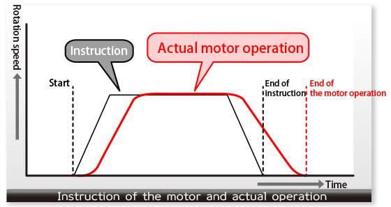
The number of revolutions is the area of the command trapezoid. The area of the actual motor operation needs to be controlled to match the area of the command.
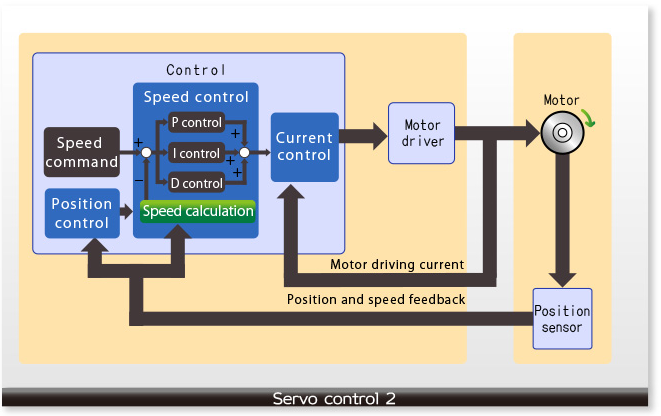
PID control
uses PID control to control the speed of servo control.
PID control will perform each control in parallel: P control (proportional control), I control (integral control), and D control (derivative control).
Since each control has a useful role, the combination of these controls can easily handle various changes. Proportional (P) control is a simple amplification: if the current value is less than the set value, the value will be controlled in the positive direction, and if the current value is larger, the value will be controlled in the negative direction. In many cases, the target value cannot be achieved using proportional (P) control, so we add integral (I) control. Integral (I) control will determine the motor drive current proportional to the total difference (integral value) according to the current state. In other words, it is a control that corrects the accumulated changes. In contrast
, differential (D) control is a control that handles unexpected states. The greater the degree of change, the greater the force of differential (D) control to restore the state to its original position. This is an effective control for the following situations: when an excessive load is suddenly added/removed, when the voltage becomes unstable or suddenly drops, and when external disturbances affect and the state needs to be restored to its original position.
Therefore, PID control can make the motor speed reach the ideal speed.
We have introduced the overview of servo control. Servo control can be easily implemented using a microcontroller.
The role of microcontrollers
In recent years, microcontrollers have been used for servo control. Microcontrollers implement servo control by software. Microcontrollers are often used as system controllers, and they control not only servo control but also a variety of things. Servo control is performed asynchronously with controls other than servo control. In addition, servo control needs to be performed regularly. If they occur at the same time, the microcontroller must give priority to either servo control or control as a system controller. But the microcontroller that receives the lower priority cannot delay until the required time. The higher the system function controlled by the microcontroller or the higher the control accuracy, the more frequently this phenomenon occurs. To avoid this, it is necessary to increase the processing speed of the microcontroller.
Generally, it can be achieved by speeding up the system clock, but this increases power consumption, which generates noise and heat. In addition, sometimes you may not be able to speed up due to the operating limitations of the microcontroller. To solve this problem, we can use several methods to reduce the processing load of the microcontroller: Use a microcontroller coprocessor for servo control and separate the hardware of servo control and system control. The programmable servo/sequence controller (PSC) can be started asynchronously with the system control and execute the servo control process. It is a single IC, but the servo control and system control are handled separately by hardware. The system clock can be kept at a low frequency.
 XINDA
XINDA