


Motor terms-What is motor resolver?
Date:2024-05-14 Author:Shandong Xinda Motor Co., Ltd.
1. Principle
Resolver is a commonly used position sensor in motor control. The function of the resolver is to accurately measure the position, speed and direction of rotation of the motor rotor, and transmit these signals to the electronic control. The motor is controlled by the software's control algorithm.
It can control the frequency and sequence of three-phase alternating current , thereby changing the speed and direction (forward and reverse) of the drive motor. When the permanent magnet synchronous motor is working, the rotating magnetic field generated by the stator coil rotates synchronously with the rotor, and the magnetic poles of the rotating magnetic field and the magnetic poles of the rotor will maintain a certain angle. What monitors the position and speed of the rotor is the resolver.
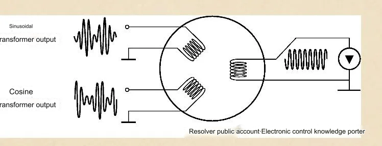
The principle of resolver: By inputting a high-frequency sinusoidal signal to the rotor coil, which is what we often call the excitation signal (the power source of the resolver), we can then receive the high-frequency induction signal fed back by the inductive resolver rotor in the coil. After processing, the corresponding sine and cosine information can be obtained, and after analysis by the software, the absolute position of the stator can be obtained.
2. Calibration
There are many popular terms for the calibration of resolvers in daily work, such as zero angle calibration, motor angle calibration, etc. Although the statements are different, the content and function are the same, that is, you need to know the angular deviation between the zero position of the resolver and the zero position of the motor.
3. Common faults
If there is a problem with the resolver, there will inevitably be a speed problem.
1. When the vehicle is static (the actual motor speed is zero), the instrument falsely reports that the motor has speed;
2. Under normal high-voltage conditions, the motor does not output speed when the accelerator
is in gear; 3. Causes a three-phase hardware overcurrent fault;
4. Causes IGBT failure;
5. Causes the motor speed to jitter;
6. Causes the motor to stall;
7. Vibrates, abnormal noise, and
the resolver harness wiring sequence is incorrectly connected. New fault: a motor passed the controller software and hardware version detection and entered NVH Under working conditions, there was a rattling noise, the characteristic curve was abnormal, and the rotation speed was negative. Finally, it was discovered that the resolver harness was designed incorrectly. 1) There are generally 6 resolver wires connected from the motor controller
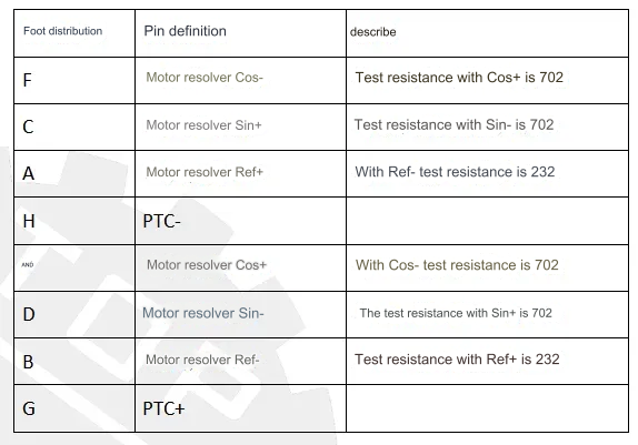
end to the motor end through the electrical detection quantity , namely: ref± (excitation signal), sin± (sine signal) and cos± (cosine signal), each group The signals have their own corresponding resistance values. You can judge whether it is a resolver fault by measuring the three sets of resolver resistance values at the motor control plug-in end or the motor end. 2) Characteristic curve
The motor speed is the accompanying signal of the motor torque, just like a gear. If you want the gear to rotate, you need an external force.
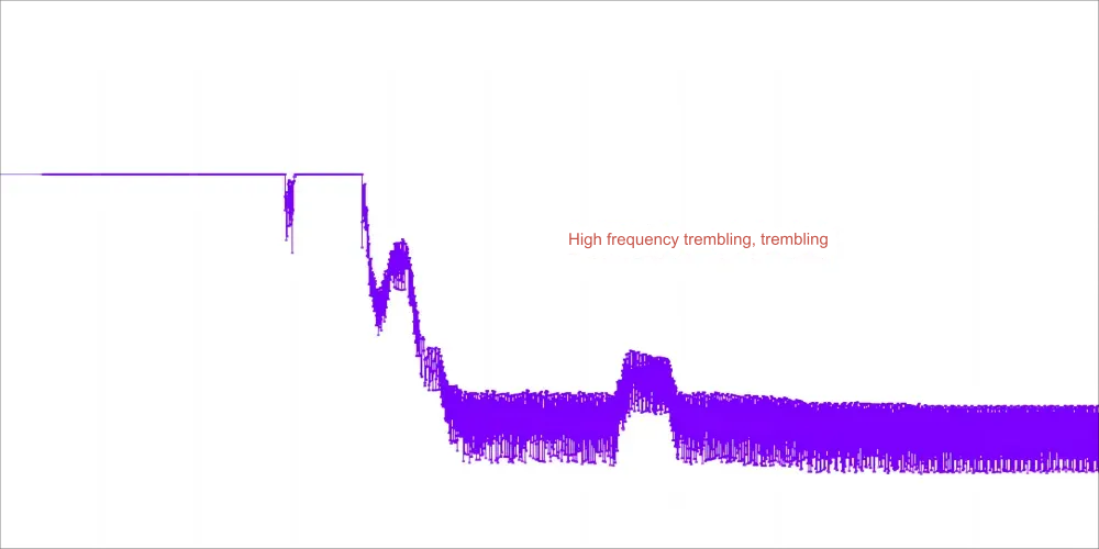
Normal motor speed changes smoothly and linearly.
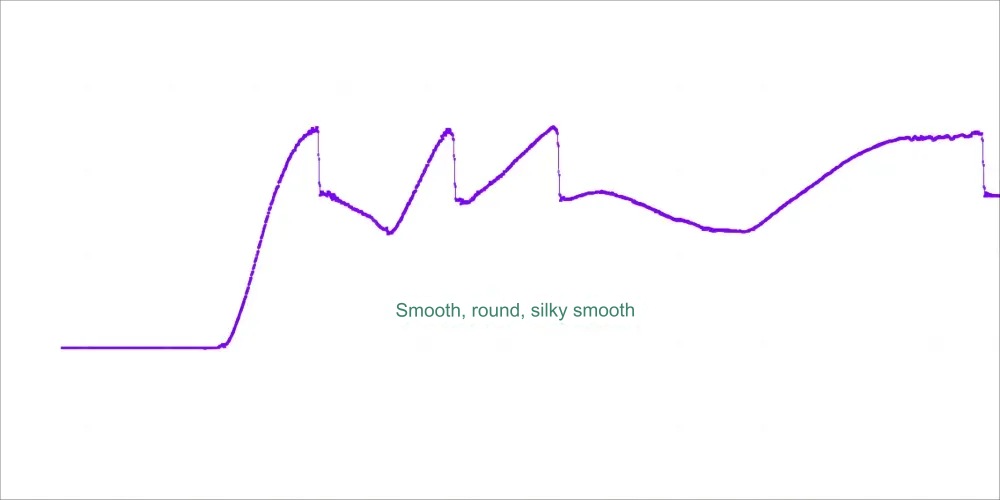
Abnormality: The motor speed curve displayed under resolver failure looks like a burr. During the driving of the vehicle, the vibration of the motor speed will cause the entire vehicle to vibrate.
One end of the resolver wire harness is connected to the low-voltage plug-in of the motor controller, and the other end is connected to the resolver low-voltage plug-in of the motor. We have the following diagnostic methods:
1) Unplug the low-voltage plug-in at the motor controller and the resolver low-voltage plug-in at the motor, and use a multimeter to measure the continuity of excitation (ref±), sine (sin±) and cosine (cos±);
2) For example, measure the resolver resistance It is normal, but it cannot be judged whether there is a problem with the virtual connection of the wiring harness and the plug-in. After installing the low-voltage plug-ins at both ends, grab the wiring harness and shake it hard. If the instrument speed fluctuates abnormally, you still need to carefully check the wiring harness and low-voltage plug-in;
3) If the resolver resistance measured is normal (from the low-voltage plug-in end and motor end of the motor controller), and the wiring harness and plug-in are confirmed to be normal, the motor controller needs to be replaced.
 XINDA
XINDA