


Overview of the current status of global high-efficiency motors
According to some studies, electric motors consume approximately 45% of total energy consumption. If we focus our analysis on one of the most energy-consuming sectors, namely industry, the share of electric motors rises to around two-thirds.
Considering that some of the machines currently in operation are obsolete, it is clear that replacing them with new, more efficient motors would have important consequences for the environment, resource development, manufacturing costs and competitiveness. For example, it is estimated that in Europe alone, replacing outdated drive technology with state-of-the-art drive technology could reduce annual consumption by 135 terawatt hours and CO2 emissions by 69 million tonnes. By evaluating the entire life cycle of the continuous operation of the motor, we can find that expenditures related to energy consumption account for a major proportion of the total cost (even more than 90%,).
As a result, in the European Union, the United States, China and other countries, regulatory schemes are in place that mandate that new equipment comply with progressively higher energy efficiency requirements. For example, according to the Minimum Energy Efficiency Standards (MEPS), motors in the power range 0.75 to 375 kW released on the EU market from January 2017 must meet the energy efficiency level IE3, or IE2 if driven by a frequency converter energy efficiency levels (see Figure 1), with very few exceptions.
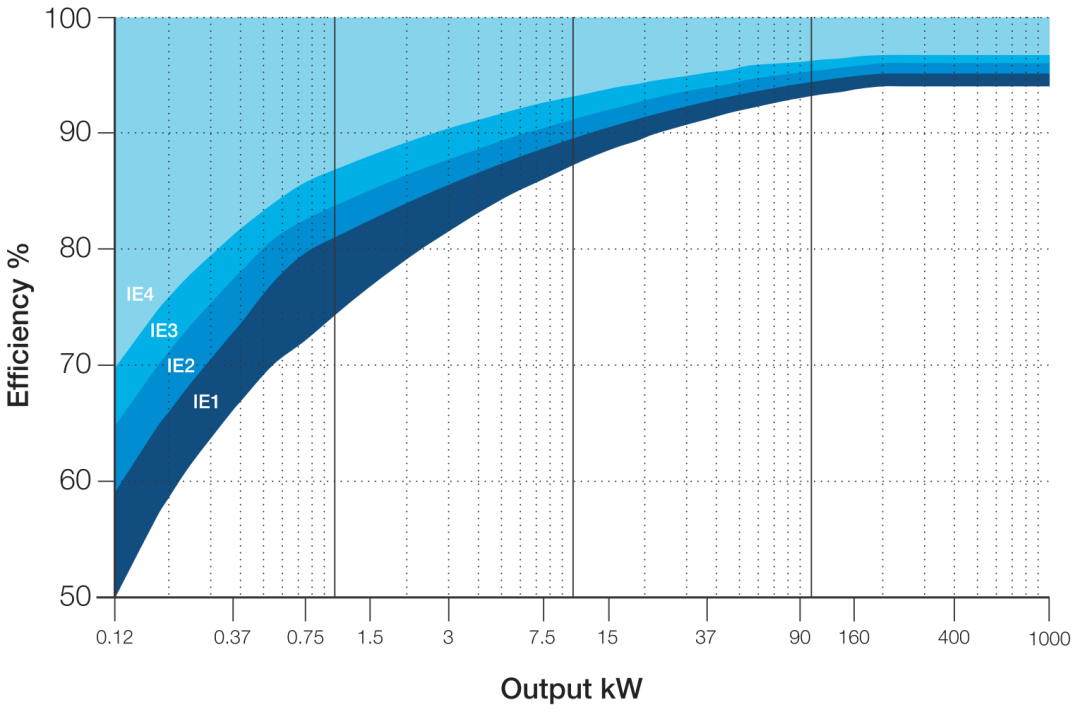
Figure 1. Efficiency values corresponding to IE classes specified in IEC/EN 60034-30-1:2014.
Currently, asynchronous motor (or induction motor, IM) technology is the most widely used in electric machines, but the required improvements are unlikely to be achieved in the future, at least at reasonable cost and across all power ranges. These aspects, together with other factors such as the growing awareness of the importance of reducing energy consumption, have led to the adoption of motors that have hitherto been rarely promoted, such as permanent magnet synchronous motors. In fact, the inherent characteristics of this type of motor can significantly increase efficiency and power density, especially the extremely low rotor losses.
Although "brushless" servo motors (i.e. surface mount-PMSM, SM-PMSM) have been used in industrial automation fields as early as the 1980s due to their excellent controllability and high dynamic characteristics, for a long time, with brushless The use of electric synchronous motors with rotors is still limited to special applications. On the contrary, in the past few years, the application of this type of motors has been expanding significantly due to the factors mentioned above regarding efficiency and the reduction in the production costs of motors and frequency converters.
Most AC motors are three-phase, but there are some exceptions, such as single-phase and stepper motors (usually two-phase). The most important difference is usually that between synchronous and asynchronous machines, which is based on the fact that in steady state the mechanical speed is strictly related (synchronously) or not to the rotational frequency of the stator magnetic field. This difference is manifested in the fact that in order for an asynchronous motor to produce torque, an induced current must exist in the rotor, whereas a synchronous motor does not (and conversely, does not require) an induced current.
Synchronous motors are characterized by the geometric binding of the rotor magnetic field to the mechanical position of the rotor itself. The rotor magnetic field can be generated by the current in the windings (synchronous machines with wound rotors), permanent magnets (permanent magnet synchronous machines) or the stator current itself, and is regulated by the magnetic anisotropy of the rotor (synchronous reluctance).
From a structural point of view, the rotor and stator of radial flow motors (currently accounting for the vast majority) are made of stacked ferromagnetic layers that are blanked in time to suppress parasitic currents. Rotors are usually cylindrical and can be equipped with spaces to accommodate permanent magnets or conductive material.
Figure 2 is a schematic cross-sectional view of the above types of motors (except synchronous motors with wound rotors).
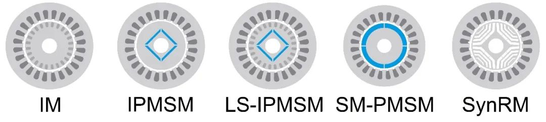 Figure 2. Various rotor configurations (left to right): asynchronous or induction motor (IM), internal permanent magnet synchronous motor (IPMSM), internal permanent magnet synchronous motor with rotor cage (line start IPMSM), surface permanent magnet synchronous motor Motor (SM-PMSM), synchronous reluctance motor (SynRM).
The darkest areas (slots) correspond to the windings, the permanent magnets are shown in blue, while the gray areas of the profile represent the ferromagnetic material (layers). As you can see, the differences between the different types of motors mainly focus on the rotor, while the stator (barring special circumstances) can be implemented in the same way. In asynchronous motors, the rotor slots are filled with melt, forming a so-called "squirrel cage", usually made of aluminum or more recently copper (at higher cost to reduce losses).
In contrast, in permanent magnet machines, the magnets can be introduced suitably engraved inside the rotor structure (IPMSM and line-start IPMSM), or applied to the surface in the case of SM-PMSM. In the case of a synchronous motor, the notches inside the rotor are simply gaps, called "flow barriers" because their role is to increase reluctance (i.e., the ability to oppose the passage of magnetic flow) in certain directions, while favoring others. (i.e. the path with more iron).
Synchronous motors, in turn, can be subdivided according to the principle of torque production. In surface permanent magnet machines, torque is generated entirely due to the interaction between the magnetic field generated by the permanent magnets and the stator current.
Vice versa, in a reluctance motor, the system tends to minimize the magnetic circuit reluctance if it is excited. In internal combustion engine motors (IPMSM), both principles are usually exploited.
When producing permanent magnets, special materials are required to obtain high induction values and prevent the risk of demagnetization (usually associated with high temperatures or high magnetic fields). The most commonly used materials are neodymium-iron-boron, samarium-cobalt and aluminum-nickel-cobalt. Especially in the case of SM-PMSM, the amount of active magnetic material is large, and the raw materials account for a large proportion of the total cost. This situation is aggravated by the highly variable prices of so-called "rare earths", which are used in small amounts but are very important for magnet quality. In addition to cost and availability issues, the mining, trade and disposal of these materials raise important environmental, political and ethical issues. For these reasons, considerable resources are invested in research and development of different materials, especially in motor projects, to minimize the use of permanent magnets or to allow the use of so-called ferrites, i.e. the use of less problematic materials Ceramic magnetic material.
One disadvantage of synchronous motors is that they cannot be powered via a simple network connection (Direct Online, DOL) like asynchronous motors. Therefore, the operation of a permanent magnet synchronous motor or a reluctance motor requires a "driver", i.e. a whole consisting of a real inverter (a purely electronic power actuator), an electronic controller and the algorithms within it. The control algorithm implemented on the digital device is updated at a frequency of 10,000 times per second. Despite the increased cost, it is worth considering that the possibility of changing operating conditions, especially speed, brings important advantages in some applications (especially pumps and fans, allowing significant energy savings).
By controlling the inverter with PWM (Pulse Width Modulation), a voltage characterized by amplitude, frequency and arbitrary phase can be efficiently generated.
Since the torque of a synchronous machine depends on the current amplitude and its phase relationship with the rotor magnetic axis, the Park coordinate transformation is often used in the control algorithm to convert the three-phase system into a reference system integral with the rotor axis (Fig. 3 ).
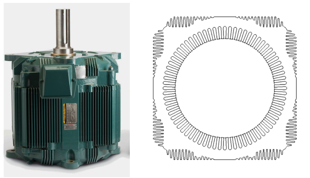
Figure 3. Left: Direct drive cooling tower motor without containment; right: Die-cut profile of the stator lamination (right) (ABB-Baldor website).
Therefore, knowing the rotor position is crucial for synchronous motor control. In some applications where special control capabilities are not required, mechanical position sensors can be eliminated due to their reduced cost and reliability. In fact, "sensorless" control techniques have been developed that use current and voltage measurements (if necessary inside the frequency converter) as well as motor models to estimate the rotor position.
Sensorless technology for synchronous motors has been developed since the 1990s and was initially only used in some special cases. This type of algorithm first appeared in the late 2000s in what are now called "inverters", i.e. in universal drives, and has become almost standard equipment in recent years. Unfortunately, despite the proven effectiveness of these solutions, especially in common applications such as pumps and fans, they are still poorly understood by automation operators.
Since the data provided by the motor manufacturer is often insufficient to calibrate all parameters of the control algorithm, "self-tuning" methods have been developed, in other words, commissioning with minimal intervention by the operator. The first step is the automatic identification of the parameters ("self-identification"), which is done by the drive itself, followed by the real calibration, i.e. the selection of the values of the control parameters. Both industry and academia are actively working on these aspects, and Italy has come up with very interesting proposals.
As mentioned before, the biggest difference between different types of AC motors lies mainly in the rotor structure. In fact, there are many synchronous motors whose design remains almost the same (only the number of winding turns is changed) compared to their asynchronous counterparts. This method has been promoted in the past few years to meet the needs of general applications, precisely as a replacement for asynchronous motors. In addition to the obvious advantages in terms of manufacturing costs, these motors can be adopted without modifying the remaining mechanical structure due to the use of equivalent components in terms of overall dimensions, supports and external fixing points.
In synchronous motors, especially permanent magnet motors, it is possible to achieve high pole counts, reducing speed at the same voltage and increasing torque at the same current. This degree of freedom in the project can be compared to the use of mechanical reducers, therefore, in certain applications it allows the use of direct drive connections, with certain advantages in terms of efficiency, overall size, cost, reliability and control accuracy. This solution has been used for many years in industrial machinery (e.g. paper making), in the civil lifting sector (elevators), in air treatment (cooling tower fans) and in some household appliances (especially washing machines).
In the project considered, the stator stack (lamination) is used as a structural element without the addition of an external casing. Figure 3 also shows the stator lamination design, where the outer wings for heat dissipation are visible. Since the overall size limits the height, the motor is mounted at the base of the cooling tower, coaxially with the fan, thus avoiding the right-angle transmission and reduction required in conventional configurations (asynchronous motors).
Initial applications of permanent magnet synchronous motors in the civil sector include air conditioning systems, where energy consumption plays an important role. In the field of refrigeration (industrial and domestic), the use of synchronous motors is also gradually increasing. Furthermore, circulation pumps in heating plants are a special case, and for efficiency reasons permanent magnet synchronous motors with sensorless control are almost exclusively used today.
In household appliances, such motors have become commonly used in washing machines in recent years. The use of synchronous motors instead of asynchronous motors or universal motors (with brushes) can, on the one hand, reduce the overall size and the amount of materials used, and on the other hand, improve controllability, which is also related to the use of solutions such as mechanical direct drive connections. In the latter case, due to overall size constraints and torque requirements, the rotor is usually external and the entire motor is flat and has a larger diameter (Figure 4).
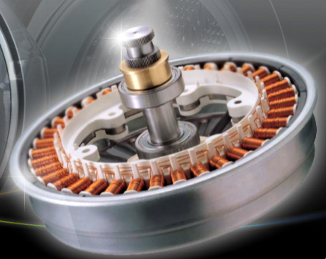
Figure 4. Direct-drive permanent magnet synchronous motor with external rotor (website LG).
A detail in the production of machines of this type, also common to other special applications, is the on-tooth winding (a different winding for each stator tooth).
In this type, there are fewer unused copper parts, but it becomes more difficult to design a machine with low torque ripple. Direct coupling also has advantages from an overall operational point of view, in addition to speed control, it also facilitates identification of the load in the tank and its arrangement.
Due to the special working cycle of the washing machine (including dehydration and drying), high speed operation (exceeding the rated speed) is very important. This mode is called "deflow" because the voltage is proportional to the flow rate and rotational speed. With appropriate control, the total flow rate can be reduced, allowing operation at a higher rotational speed and fixed voltage. In this case, an internal permanent magnet synchronous motor is the main choice because its available torque does not drop suddenly outside the rated speed.
Synchronous motors are widely used in lifts, especially large lifts. In this case too, a special solution is used, as shown in Figure 5, allowing direct load movement (without gears).
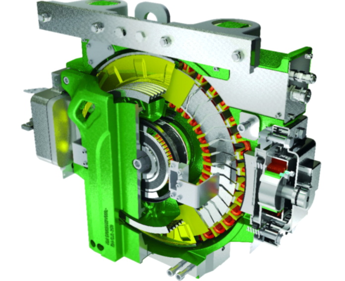
Figure 5. Gearless elevator hoisting system equipped with axial permanent magnet synchronous motor (website Kone).
In this case it is an axial flow motor, i.e. the gap (magnetic gap) between the stator and rotor is crossed by magnetic field lines parallel to the axis.
Other specific application areas involve renewable energy (such as wind power) and avionics, which pursue the goal of "more electric aircraft" (replacing hydraulic or pneumatic actuators). The use of high-efficiency and high-density electric motors is also expanding in the traction sector, including on the road (from bicycles to heavy vehicles and operating machinery), in the railway/tramway sector and in the industrial sector (forklifts and similar equipment).
 XINDA
XINDA