


Detailed analysis of motor winding technology
Motor winding is done by placing the wires within the coil into slots, which are usually wrapped in a coated, flexible ferromagnetic core to form the magnetic poles. Motors have two basic pole configurations, salient and non-salient. The stator is wound with pairs of coils corresponding to the phases of electrical energy. The stator of a 2-phase induction motor has 2 pairs of coils, each pair of coils corresponding to one AC phase. Each pair of coils are connected in series and correspond to the opposite poles of the electromagnet. One coil corresponds to an N pole, the other corresponds to an S pole, and the other pair of coils is 90° spatially to the first pair of coils. In the case of a two-phase motor, the pair of coils are connected to the AC coil with a time offset of 90°, and the motor winding diagram is shown below.
Winding connection method
In a salient pole motor, the magnetic poles can be produced by windings wound under the pole face, and in non-salient pole configurations, the windings can be dispersed within the pole face slots. A typical shaded pole motor consists of windings placed around a pole that supports the phase of the magnetic field. Some types of motors include conductors, which are made of thick metal sheets. The metal strips are usually made of copper or aluminum. Depending on the type of starting method used for the motor, the three phase windings of the motor are connected in star or delta. Motors such as squirrel cages can frequently run on rails via a star connection to a triangular stator.
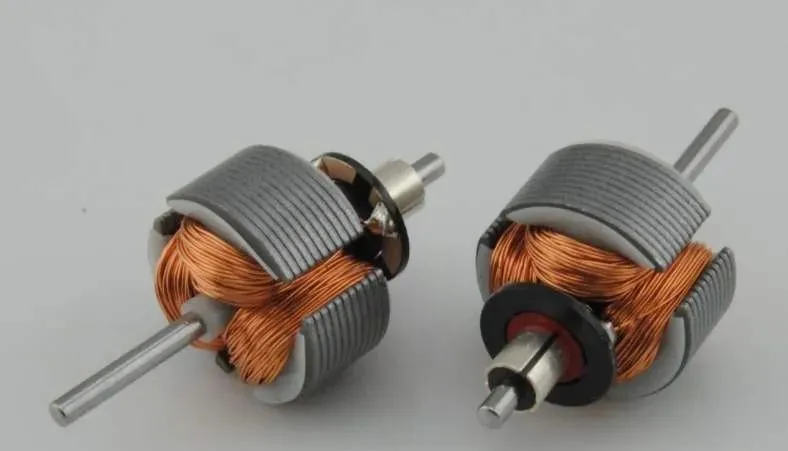
The windings of both two-phase and three-phase motors are installed in stator slots. The coils are wound around external fixtures and then wound into the slots. An insulation layer sandwiched between the coil periphery and the slots prevents wear. Windings are made of copper wire wound around an iron core and are used to create or obtain electromagnetic energy. The most commonly used winding material is enamel paint-wrapped copper or aluminum wire, consisting of a set of coils in slots and teeth in the edge area of the windings.
In large motors, the pole windings are divided into bundles of identical coils, which are inserted into smaller slots. The groups are called phase strips (see figure below). The distributed coils of the phase band cancel some odd harmonics and produce a sinusoidal magnetic field distribution on the magnetic poles. Since the phase bands can overlap, slots at the edge of a pole may have fewer turns than other slots, and edge slots may contain two-phase windings.
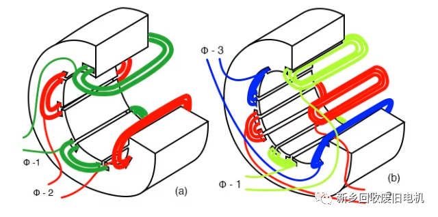
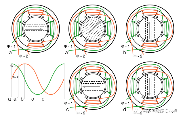
The rotating magnetic field is generated by two coils at right angles to each other and driven by 90° out-of-phase currents. Three windings are placed 120° apart in space and powered by corresponding 120° phase currents. A rotating magnetic field will also be generated. When As the 90° phase sine wave moves from point (a) to point (d), the magnetic field rotates counterclockwise (Figure ad).
The rotation speed of the stator's rotating magnetic field is related to the number of pole pairs per phase. The "full speed" diagram below has a total of 6 poles or 3 pole pairs and 3 phases. Each phase has only one pair of poles. The magnetic field rotates once per sine wave cycle. In the case of 60HZ, the magnetic field rotates at 60 times per second or 3600 revolutions per minute (rpm), and for 50HZ it rotates at 50 revolutions per second or 3000 revolutions per minute. If you double the number of poles in the motor, the synchronous speed is halved because the magnetic field rotates 180° in space, producing a 360° sine wave.
In order to effectively wind the pole slots of the electronically commutated multi-pole three-phase motor tightly together, they will be coated with insulation and directly wound using the needle winding method. A needle with a nozzle, moving in a lifting motion at right angles to the direction of movement, passes through the stator group through the channel between two adjacent poles of the motor, dropping the wire in the desired position.
The stator is then turned one tooth pitch at the reversal point on the winding head so that the previous process can be run again in reverse order. Specific layer structures can be achieved with this winding technology. The disadvantage is that there must be a gap between two adjacent electrodes. The size of the gap is at least the diameter of the nozzle, which is approximately three times the diameter of the winding. The space between adjacent poles cannot be completely filled. The figure below shows the right-angle winding method.
The advantage of needle wrapping technology is that the needle holder carrying the guide wire nozzle is usually coupled to a CNC coordinate system, which allows the nozzle to move through space towards the stator. In this way, in addition to the normal lifting movement and rotation of the stator, a laying movement can also be performed. Since the copper wire is pulled out from the copper wire guide nozzle at an angle of 90°, the copper wire can only be placed directionally within a limited range.
Since the guide wire nozzle can move freely throughout the trough, the nozzle can terminate the wire at the contact point if equipped with an additional swivel device. As with traditional linear winding technology, contact pins or hook contacts can be in close contact with the moving surface and are suitable for single-pole interconnections in star or delta connections. The figure below shows the winding method with an angle of 45°.
The rotational and stroke movements need to be precisely synchronized so that the needle does not contact the channel during the up and down movement. The variables that affect the maximum winding speed are: needle travel, stator rotation angle (number of poles), wire diameter, channel width, skew Stator helix angle. Because the wire guide and needle holder move at high accelerations, this can cause unwanted vibrations that affect winding quality. Lifting mass is typically produced by a ball screw, and during this movement the servo drive must continually reverse to accommodate the opposite movement of the wire guide.
in conclusion
With pin winding technology, finished components such as stator coils or connections can be produced. In addition to the underutilized space between the poles, motor coils with a good fill factor can also be wound to a lower stator lamination height (coiler head height) compared to conventional pull-in technology.
 XINDA
XINDA